Intel® RealSense™ Self-Calibration for D400 Series Depth Cameras
Anders Grunnet-Jepsen, John Sweetser, Tri Khuong, Sergey Dorodnicov, Dave Tong, Ofir Mulla, Hila Eliyahu, Evgeni Raikhel
Rev: 2.7
This article is also available in PDF format
1. Introduction
Intel® RealSense™ Depth Cameras D400-series are based on calculating depth from stereo vision. All sensor modules are built from factory to be extremely sturdy, encased in laser-fused steel cages, with the intent of maintaining calibration and performance over their lifetime. However, conditions can occur that lead to degradation over time, such as exposure to extreme temperature cycling, or excessive shock and vibe. Whatever the cause, Intel provides a set of tools to recalibrate cameras back to their pristine factory condition. These tools include “OEM calibration” based on targets, as well as some “Dynamic Calibration” methods that can restore performance in the field.
In this whitepaper we introduce a set of Intel RealSense™ SDK2.0 (aka LibRealSense) components that we call “Self-Calibration”. They are meant to 1) Restore the depth performance, and 2) Improve the accuracy, for any Intel RealSense™ Depth Camera D400 series that may have degraded over time. The main components of Self-calibration work on any Operating System or compute platform, as they simply invoke new Firmware (FW) functions inside the ASIC. As a result, they also have essentially zero load on host CPU and are very fast. Two new functions (described in Addendums) run over the host and add extra calibration capabilities and accuracy. Other benefits of these new functions are that they require no motion or repositioning during calibration, and they can complete in seconds. So how often is it required to run these self-calibration techniques? It may indeed never be required, as RealSense cameras are designed to maintain calibration. However, these tools can also serve as a validation that a device is performing to its limits, in that it is possible to run these calibration routines and compare the performance before and after, without permanently updating the new calibration inside the camera. We refer to one of these features as the “Health-Check” function that will give a direct metric of the calibration state, that can be monitored over time, without the need for special targets.
In next sections, we describe each self-calibration method, its instructions, benefits, and restrictions. Each of the components can be used independently, but when using more than one we will recommend specific flow. The full recommended flow is documented in Appendix B.
2. Depth Noise
2.1 Defining Depth Precision##
We start by introducing a new method for restoring the camera to optimize its depth performance in terms of minimizing depth noise. To be specific, this first method focuses on the ability of the cameras to see objects and report back their position with low noise. In other words, we improve the precision, or relative error. In section 2 we will focus on improving the accuracy, or absolute error.
When D4xx cameras degrade in performance, they tend to do so by gradually showing more noise in the depth map. This noise can be best visualized by looking at a textured flat wall where the amount of bumpiness (depth variation) will increase as the units go more out of calibration, until the depth measurements start failing altogether, returning values of 0 indicating invalid depth. At this point the nearly 100% “fill ratio” diminishes quickly, and “holes” start to appear in the depth map.

Figure 1. Comparisons of the Point Cloud of a well calibrated camera (LEFT) with a degraded camera (RIGHT) for a flat textured wall. The lower bumpiness on the left is preferred.
To quantify the depth precision (relative error), the cameras can be pointed at a flat target, like a wall, and depth can be measured at every point in a small section of the Field-of-View (FOV), typically a 10%-20% region-of-interest (ROI) near the center. This ROI depth map is then fitted to a plane, and RMS Depth noise is measured as the standard deviation from this plane. While this can be reported in absolute units, like 5mm for example, the best way to compare depth performance across cameras, depth ranges, resolutions, FOV, and projector variations is to use the normalized metric called the Subpixel RMS value:
Subpixel RMS equation
Where the Depth RMS error is the noise of a localized plane fit (generally the “bumps” or in some cases “egg carton effect”), focal length is the depth sensor’s focal length normalized to depth pixels, Baseline is the distance between the left and right imagers, Distance is the range to the wall, HFOV is the horizontal field-of-view of the stereo imager, and Xres is the depth map horizontal resolution at which the measurement is done, for example 1280 or 848. The HFOV, Baseline, and Focal Lengths can be obtained by querying for the camera intrinsics and extrinsics using the Intel RealSense SDK 2.01. The D415 has a nominal HFOV ~65° and baseline of ~55mm, while for the D435 the HFOV is ~90° and baseline is ~50mm.
2.2 Example Target for Calibration & Characterization##
When running the on-chip Self-Calibration routine, the ASIC will analyze all the depth in the full field-of-view. However, since it can sometimes be difficult to ensure there is good texture in a full FOV, we have enabled a new resolution mode of 256x144 which outputs the zoomed-in central Region-Of-Interest (ROI) of an image, reduced by 5x in each axis from 1280x720. Figure 2 shows an example of a D435 pointed at a wall with a small target, using the full FOV, and the better suited smaller FOV.

Figure 2. Full Field-of-view of a D435 camera, vs a central region-of-interest zoomed-in view with resolution mode 256x144 (zoomed in 5x from 1280x720). The smaller resolution mode is recommended for calibration.
The smaller ROI is especially well suited to looking at an A4-size target, such as that shown in Figure 3, and reproduced in Appendix A so it can be printed out.
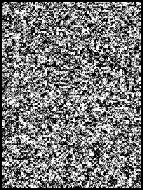
Figure 3. Example A4-sized target with texture which is particularly well suited for both on-chip calibration and depth quality characterization. The exact nature of the texture is not critical, as long as it is semi-random and fairly “noisy” with high spatial frequencies.
2.3 Running the Self-Calibration routine##
The process for running the on-chip self-calibration is straight-forward and is separated into three steps. 1. Run the self-calibration routine, 2. Validate the improvement, and 3. Burn the result permanently into Flash memory . Before embarking on this it is important to make sure that the Intel RealSense™ Depth Camera D400 has the latest Firmware (FW version: 5.12.02.100 or later) that includes the self-calibration features, and LibRS version 2.33 or later .
In the following we describe the measurement set-up and the programming details. We will then show how this can be tested immediately using the latest Intel RealSense Viewer or Intel RealSense Depth Quality Tool, requiring no knowledge of the underlying programming.
We start by describing the recommended set up. While the main rule of thumb is that the camera can be pointed at any scene that would normally generate >50% valid depth points, we emphasize here the value of getting up and running under more ideal conditions.
As a good reference, you can print the textured target attached in the Appendix A and fasten it flattened to a wall. Note that the flatness has no impact on the self-calibration process itself, but it will have a significant influence on how well it is possible to characterize and validate the results afterwards if that is desired. In general, any natural scene with sufficient texture will work, as described in Section 2.4.
Place the camera far enough away that it is beyond the minimum range (aka, MinZ) of the depth camera, but close enough that at least 35% of the target texture is visible in the image. Ideally it should fill the zoomed-in ROI. With this setup the color and depth map should look like that in Figure 4. It is not critical that the wall be exactly perpendicular to the camera’s Z-axis.

Figure 4. Example zoomed-in 256x144 image of a D435 monochrome image (from left imager) and depth map, as observed by looking at a textured target mounted on a flat wall. The black bar on the left is expected and acceptable. In general, it is important to have >35% of the depth map show depth values (non-zero). In this example the IR projector was left on, but we recommend turning it off when pointing at a well-textured scene.
Figure 5 shows a few different examples of target placements. While all these setups work, the one described in the bottom guarantees best performance and robustness.
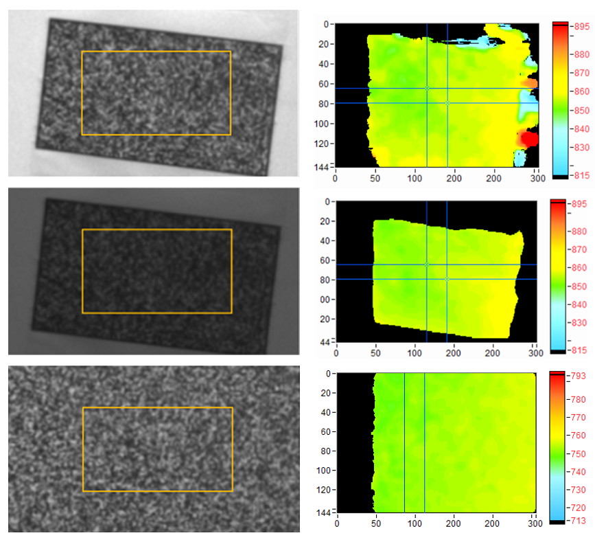
Figure 5. Examples of different set-ups. TOP: Not filling FOV, and not using projector. The depth map shows some noisy depth on the right side. This configuration works but is not recommend. MIDDLE: Not filling FOV, but changing depth setting from default (high density) to High-Accuracy, with manual exposure. The noisy depth is now removed. This is better than before. BOTTOM: Moving closer and filling the FOV completely with the target. This is the preferred configuration. The tilt of the target does not matter.
Now we turn to the actual flow of commands. We have 4 self-calibration steps in the Intel RealSense SDK 2.0 related to recovering the depth performance. Here is the high-level flow. For a more detailed API description please see the Appendix B:
// 1. Get pointer to current calibration table, before running on-chip calibration.

CalTableBefore = rs2_get_calibration_table();

// 2. Runs the on-chip self-calibration routine that returns pointer to new calibration table.

CalTableAfter = rs2_run_on_chip_calibration();

//3. Toggle between calibration tables to assess which is better. This is optional.

rs2_set_calibration_table(CalTableAfter);

// 4. burns the new calibration to FW persistently.

rs2_write_calibration();
- Get pointer to current calibration table, before running on-chip calibration.
- Runs the on-chip self-calibration routine that returns pointer to new calibration table.
- Toggle between calibration tables to assess which is better. This is optional.
- Burns the calibration to FW persistently.
The rs2_run_on_chip_calibration command is a blocking call that has speed as an argument:
0 = Very fast (0.66 seconds), for small depth degradation
1= Fast (1.33 seconds), medium depth degradation.
2= Medium (2.84 seconds), medium depth degradation.
3= Slow (2.84 seconds), for significant depth degradation.
There is a tradeoff between scan speed and degree of degradation. For slight degradation, “Very Fast” or “Fast” is acceptable, but for severe degradation, “Slow” may be necessary. In most cases, the recommended speed is “Medium”, which takes ~2.8 seconds to complete when running at 90 fps and scales in speed with frame rate.
The self-calibration algorithm is currently designed to correct for either “intrinsic” or “extrinsic” errors, but not both at the same time. Intrinsic errors come about primarily through microscopic shifts in the lens positions. Extrinsic errors are related to microscopic bending and twisting of the stiffener on which the two stereo sensors are mounted. The user can select which mode to run, using the Mode selection in the function call. The “intrinsic mode” is selected by default and is normally the recommended mode. The main observable differences appear in the edges of the FOV, for very impaired cameras. While both modes correct the central 20% of the FOV, they differ in how they correct the edges of the FOV.
So how is the user supposed to know whether to run intrinsic or extrinsic correction? For sufficiently small degradations, where self-calibration is recommended to be used, there is little difference, and it does not matter. For larger degradations, it depends on the type of physical impairment the camera most likely suffered. For example, if an operator is mounting a camera module, the cause is most likely extrinsic, e.g., bending or twisting of the stiffener. If one of the lenses was touched, it is most likely intrinsic. Whenever there is no clear root cause, the recommendation is to use the “intrinsic mode”.
Once the calibration has been performed, the ASIC will leave the new calibration active, but will not have burned it automatically to flash memory. This allows the user time to confirm whether the performance is indeed improved. One way to validate the performance is to point to a flat textured surface and calculate the RMS Subpixel error, as described earlier, and compare the before and after values. The rs_set_calibration_table function allows for switching back and forth if needed to compare calibrations.
We should note that, in principle, this self-calibration function always finds the optimal calibration, and if it does not, then it returns an error. The exception will then be raised via standard rs_2_error protocol.
One of the extremely powerful aspects of the self-calibration algorithm is that it also performs an on-chip “Health-Check”, that does not require any specific visual target. Basically, once a self-calibration has been run, the health-check number will indicate the extent to which calibration deviates from ideal. If the absolute value is below 0.25 then the camera is nearly optimally calibrated, as shown in Table 1. Any value above this means the camera performance can be improved through re-calibration. Moreover, if the absolute value is larger than 1 then the unit is essentially non-functional without recalibration. The sign of the Health-check is mostly for diagnostic purposes, as it indicates the polarity of the error. This health-check number can also be very valuable to some users in allowing for a simple diagnostic that can be monitored over time.

Table 1. The “Health-Check” indicator will return a measure of the need for recalibration. While units are operational for values below 1, it is optimal to have an absolute value below 0.25. This health-check does not need any special target.
In any event, provided the new depth performance is deemed better by the RMSE measurement or by the ASIC Health-Check number, it is now advisable to burn the calibration to the flash permanently. After burning the new calibration to ASIC, we recommend running on-chip calibration one more time to confirm that health-check number is now low. You can run this at “very fast”.
It is also important to note that there is always a way to recover the original factory calibration if some bad calibration has inadvertently been written to flash. This is done by calling the function called reset to factory calibration.
We note one more important aspect. We developed a special calibration mode for the case of pointing the D400 Series cameras at a white wall that has no texture while the laser pattern projector is turned on. It turns out that this special case can be troublesome due to the semi-regular laser pattern of the D415 projector. This mode of operation can be selected under the “speed” settings and is called “white wall”. It is also highly recommended that the “High Accuracy depth settings” be used during any white-wall calibration run. If not, then the ASIC will most likely return an error. However, to be clear, we do not recommend using a white wall for self-calibration for the D415. A textured surface with the projector turned off using medium speed is the recommended method for on-chip calibration of D415 cameras. On-chip calibration of D435 or D455 cameras does not require the “white wall” mode regardless of target type and projector setting; one of the standard speed settings is recommended under most conditions.
Note for D455 users: The on-chip calibration procedure should be done with thermal loop configuration off, which is done by default when using the RS Viewer or Depth Quality Tool. See python example code referral in Appendix C.
2.4 Extending to Beyond Simple Flat Textured Target##
We have seen how the on-chip calibration technique works under controlled and ideal conditions. Now we look at deviations from this. It turns out that on-chip calibration is fairly robust and works quite well under a wide variety of conditions. The primary requirement is the presence of good texture in the scene. Another way to say this is that if a healthy D400 depth camera has a good depth map with a high fill ratio while looking at the scene, then the scene will probably be well suited for on-chip calibration. The scene does not need to be flat or even static (though this is preferred when possible). The texture can be applied by a projector, or it can be a natural part of the scene. It works in complete darkness (with a projector), or outside in bright sunlight.
Figure 6 shows a non-exhaustive set of examples of scenes that work quite well. Scene “A” is the ideal scene we described previously, of a well-textured flat target with the projector turned off. Scene “B” is a flat white wall with a projector turned on. Scene “C” is a textured carpet, which is usually easy to find. Scene “D” is a cluttered desktop. Scene “E” is a flower on a table top. Scene “F” is paving stones on a patio, outside in bright sunlight. Scene “G” is a face indoor with projector turn on, and “H” and “I” are faces indoors and outdoors without projector. These are non-exhaustive or specific and are only meant to serve as examples we have tried and confirmed work well.

Figure 6. A set of scenes that have successfully been used for self-calibration, ranging from the ideal flat textured target without projector illumination (A), to scenes with projector on (B, D, E, G), to outdoor scenes in bright sunlight (F, I).
2.5 Using Intel RealSense Viewer for On-chip Calibration##
To make it easier to get familiar with the capabilities of these new calibration features, we have added them to the Intel RealSense Viewer and Depth Quality Tool, as shown below.
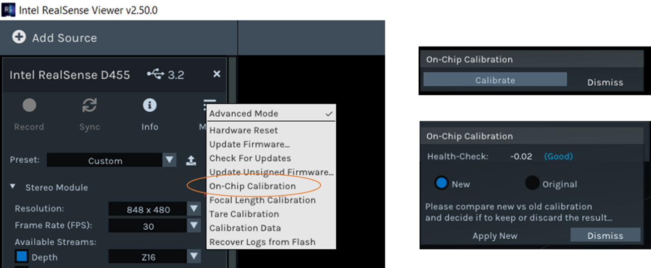
Figure 7. The on-chip self-calibration functions can be accessed in the Intel RealSense Viewer app. Once the calibration routine has been run, it will provide the result of Health-Check and ability to toggle between old and new calibration table. “Apply New” will burn it to flash on the camera and “Dismiss” will cancel the operation and keep the original calibration.
Once the on-chip calibration has been selected, the Viewer will automatically select the 256x144 resolution during calibration and will return to full resolution afterwards. During the calibration the left Monochrome (or RGB) imager can either be on or off. The Health-Check number is returned as the normalized “Calibration Error”, where an absolute value of less than 0.25 is acceptable though values closer to 0 are preferred. The user can subsequently toggle between the original and new calibration before deciding whether to apply or dismiss.
3. Depth Accuracy
We turn now to the functions to improve the depth accuracy of the Intel RealSense cameras D400 Series. The depth accuracy relates to measuring exactly the true distance. Figure 8 shows two measurements of measured distance vs ground truth distance. This result was collected by translating an Intel RealSense depth camera D435 away from a wall, while carefully measuring the average distance to the wall with the depth camera. Note that these tests were run with the Advanced Depth parameter “A-factor” set to 0.08. Please see separate white paper1 on how this improves the subpixel linearity. In the left figure there is an offset of about 1.2% in measured depth vs true depth. Also, the slope is slightly different. In the right image, the two curves overlap, and the error (shown in the lower graph) is seen to vary by about +/-0.2% around 0.
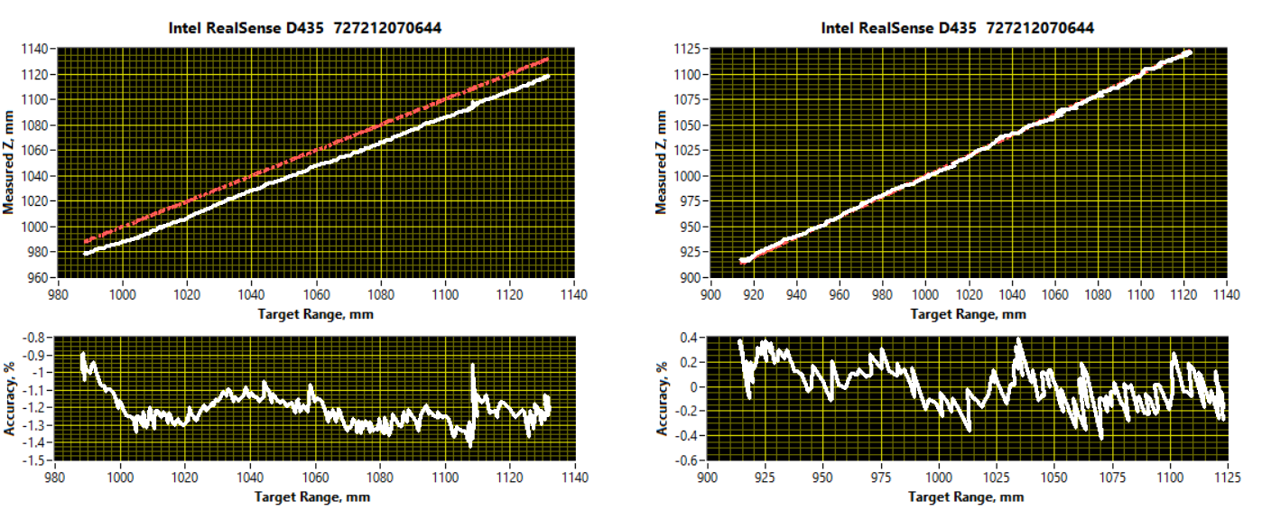
Figure 8. The measured distance vs ground truth (aka target depth). LEFT shows a calibration with a BIAS of -1.2% near 1m distance. RIGHT shows the corrected calibration where the absolute accuracy is mostly limited by the noise of the measurement.
To correct the absolute distance measurement usually involves correcting both the slope and offset of the depth measurement vs distance. We introduce a new on-chip function we call “Tare” (rhymes with “bear”). This is a function commonly used when measuring weight with a scale, as shown in Figure 9.
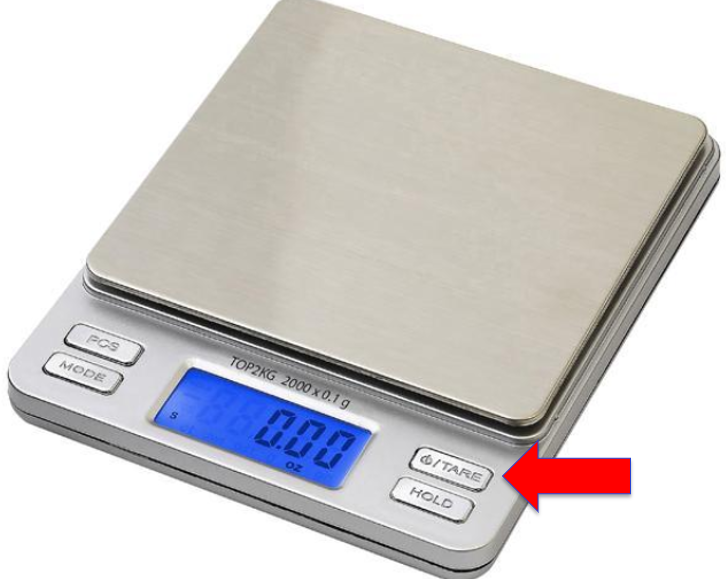
Figure 9. The “Tare” function is commonly used to remove bias and reset to a known value. When weighing objects, this means it is possible to place a bowl on a scale, “tare” to set to zero, and now measure the true weight of its contents.
3.1 Running the Tare Routine##
The “Tare” command for the Intel RealSense depth cameras D400-series requires that the user tells the ASIC the known ground truth (GT) distance measured as the perpendicular distance from the left camera’s origin to the target. This GT can be measured ahead of time in several different ways. For example, the user can place the camera into a fixture in which the ground truth distance has been carefully measured. Alternatively, the GT can be calculated on-the-fly using computer vision techniques, such as imaging and measuring a target of known dimensions. One such target and associated algorithm are described in Addendum A, “Tare Calibration with Ground-Truth Target”.
Before proceeding, we should mention that one should not underestimate the challenge associated with performing a good GT distance measurement. If using a laser range finder or “distance meter”, be sure to reference the GT distance to the origin of the left imager. The origin location depends on the specific model but is typically 1 – 4mm behind the front cover. Exact values can be found in the D400 datasheet. Make sure to use a laser range finder with sufficient resolution, that itself has been properly calibrated and certified. Many off-the-shelf range finders have accuracy specs of 1/16” or +/-1.5mm. Finally, make sure that the target is completely flat and oriented perpendicular to the camera’s pointing direction (or optical axis). Also, make sure that the depth map is good (possibly by running On-Chip Self-calibration first and burning results to ASIC). If the original depth map is not good and flat, then you cannot expect a good tare result. For best results use a textured patterned wall (or paper target), and not a flat white wall with projector turned on.
Turning now to the software command flow, it follows the same logic as for on-chip calibration. The main function is called rs2_run_tare_calibration.
Again, the process is to start by calling Tare calibration with the argument being the known GT depth. Note that the depth being calculated on-chip is the average depth to the full field-of-view.
Even though the Tare function is performed at a single distance, the process will generally help improve the accuracy across the entire depth range. This command starts an on-chip calibration routine that will take from 30ms to 1 second to complete. This is also a blocking call.
To Burn the result to Flash, the final step is writing the new calibration.
We highly recommend that before running Tare calibration the camera depth preset be changed to “High Accuracy Depth” mode. This will allow the function to complete successfully with the default chip setting of “Very High” accuracy. After the Tare has completed, the camera depth settings can revert to whatever was used previously.
Note for D455 users: The Tare procedure should be done with thermal loop configuration off, which is done by default when using the RS Viewer or Depth Quality Tool. See python example code referral in Appendix C.
3.2 Using Intel RealSense Viewer for Tare##
To make it easier to get familiar with the capabilities of these new calibration features, we have added them to the Intel RealSense Viewer and Depth Quality Tool, as shown below.
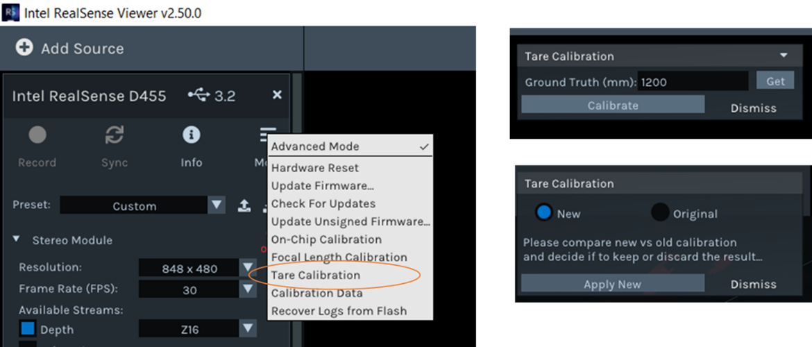
Figure 10. The tare functions can be accessed in the Intel RealSense Viewer app. A ground truth value needs to be entered, or use Get option which will be explained in next section.
To activate the functions, first set up the camera as described above and enter a GT distance to the flat target (the Get option will be described in Addendum 1) and press Calibrate. The Viewer will automatically select the 256x144 resolution during calibration and will return to full resolution afterwards. During the calibration the left Monochrome (or RGB) imager can either be on or off. The user can subsequently toggle between the original and new calibration before deciding whether to Apply New or Dismiss.
4. Limitations – On-Chip and Tare Calibration
As stated earlier, the on-chip self-calibration functions are quite robust and work well under a variety of conditions. As a general guideline, conditions under which “good” depth would be expected in the central 20% ROI, should provide good self-calibration results. The Tare function has the added requirement of a flat surface at a known distance over the same 20% ROI. Although depth noise is not required to be small for Tare to work, it is nonetheless recommended to run the on-chip self-calibration before running Tare.
Despite the robustness of self-calibration, we have identified a few specific scenarios that may lead to warnings (a.k.a. failures) and these are to be avoided. In almost all cases, the correct error message will prompt the user to adjust the conditions (speed, scene etc.), and the calibration will be prevented from updating. However, though very rare, there are extreme corner cases where we have observed that the function completes successfully but results in a calibration worse than the original. We will describe both scenarios in more detail below:
A. Self-Calibration & Tare Errors prompting a retry:
The most likely scenario for an error message for on-chip calibration is when there are not enough valid depth pixels (i.e., fill ratio too low). This can usually be remedied by ensuring that the projector is on, and the scene does not include shiny/specular or completely black/absorbing objects. Failures can also occur when the on-chip calibration algorithm fails to converge which is most likely to occur for severely degraded cameras, or on the D415 pointed at white wall but “White Wall” mode is not used. Figure 11 shows examples of such error messages.
Tare calibration should very rarely fail to converge, but 3 scenarios where this is possible are i) when “high accuracy” depth setting is not used, ii) when the camera calibration is severely degraded such that there is very low fill ratio or very high depth noise, or iii) the Z error is very large such that the input ground truth is very far from the current reported depth requiring a significant change in calibration parameters. The corresponding error message is shown in Figure 11.

Figure 11. A scenario where on-chip calibration may fail due to insufficient texture. The central 20% ROI is mostly invalid leading to the corresponding error message (LEFT). In most cases, turning the projector on will provide the necessary texture when the scene is lacking. On-chip calibration or Tare may fail to converge in cases of very large initial error resulting in error messages shown (MIDDLE & RIGHT).
B. Incorrect Result
An incorrect result, where the calibration error determined by the on-chip calibration or tare function is substantially different from the actual error, requires specific scenarios to occur. We have observed that on-chip calibration can return a bad health-check value in cases where the depth fill ratio changes significantly during the scan. While this is rare, it can occur, for example, in a scene with fast motion of camera, on scenes that have highly varying texture, and with projector turned off. All these conditions need to apply simultaneously, so simply ensuring one of them is good will lead to good results. The failure is illustrated in Figure 12.
Another scenario where on-chip calibration can possibly return a bad health-check number, is when pointing at a glossy surface with the projector turned on, so this scenario should also be avoided.
The only known scenario where the Tare function can result in a significant Z error vs the entered ground truth is when the function is implemented without the “High Accuracy Depth” preset selected as described in Section 3. While there are some scenarios that do not require this mode of operation (e.g., a very well textured target), it is generally recommended to ensure accurate results.
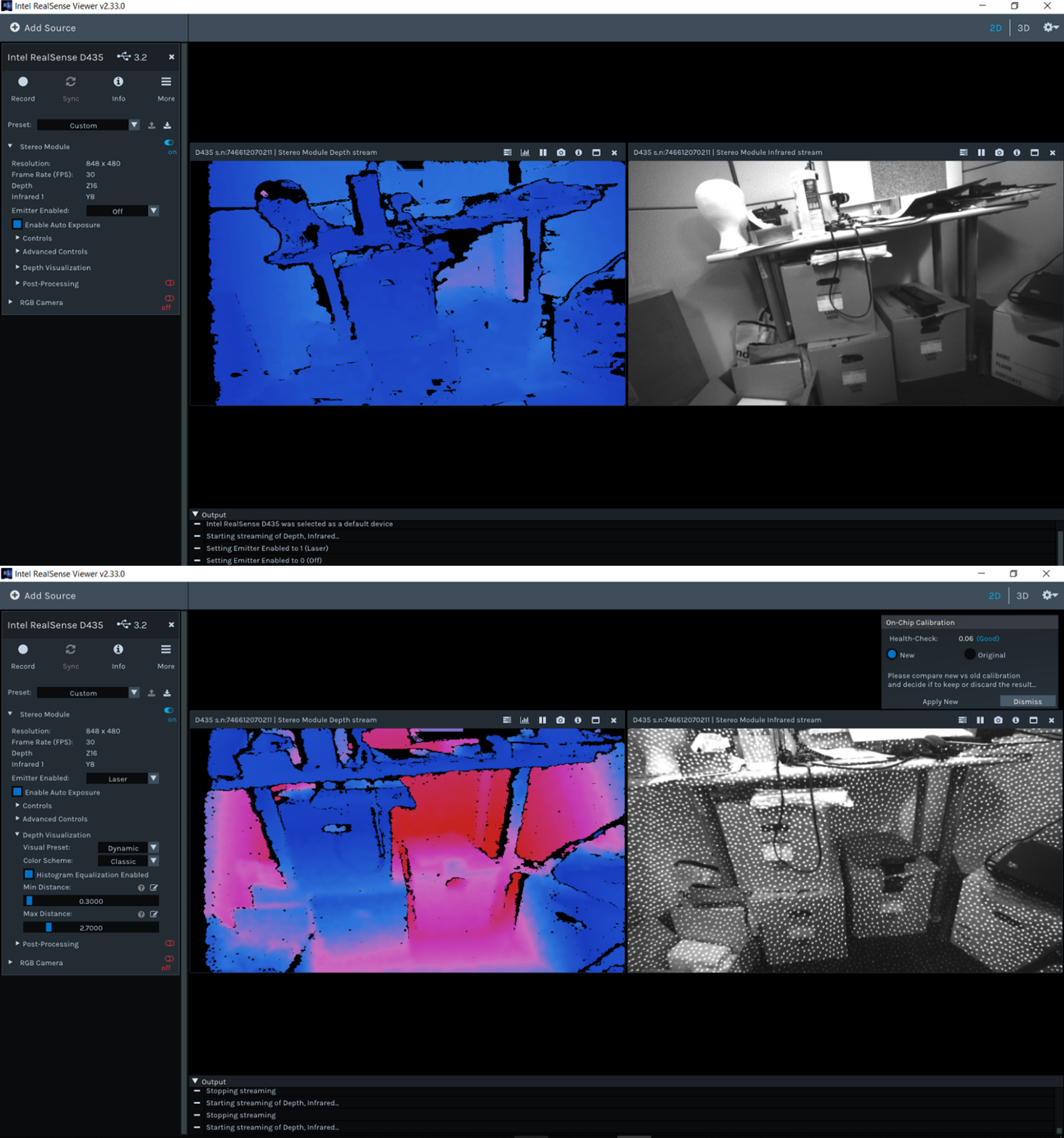
Figure 12. A scenario where on-chip calibration may result in a bad calibration. A scene with variable texture, projector off, and where camera or scene is moving while on-chip calibration is run (top) can lead to an incorrect health-check error and degraded depth. If on-chip calibration is run in a similar manner but with projector on, providing stable texture, then a more accurate health-check number will be returned, and optimal performance is obtained (bottom).
Please use the latest SW available2 and check the Errata3 for other existing issues.
5. Conclusion
We have presented methods for performing user calibration of Intel RealSense™ depth cameras D400-series. The main methods of on-chip and tare calibration are performed on-chip which means that they are simple, fast, consume little power, and work across all operating systems and platforms. These methods are generally meant to be used to fine tune the performance and are not intended to perform a complete factory calibration. These functions address some of the most common sources of calibration degradation. The self-calibration methods may not improve all units, which is why we have separated the functions into two commands: One for performing the calibration and one for burning the calibration to flash. This allows the user to first validate the new calibration before making the decision to keep or discard the new settings. In most scenarios, the Health-Check number that is generated is a very accurate and repeatable measure of the quality of the existing calibration and can be relied on without requiring user intervention or flat wall characterization.
Two new functions described in Addendums A and B, Tare with GT target, and Focal length calibration, run on the host and use a dedicated target. The first provides an optional but convenient means for accurately determining the ground truth distance for the on-chip Tare and the second provides a solution for cases of focal length imbalance. Please see the Addendums for details on when and how to use these functions.
Collectively, the self-calibration techniques are found to be quite robust but work best when following the recommendations and configurations in this paper.
References:
- Subpixel Linearity Improvement for Intel® RealSense™ Depth Camera D400 Series: https://dev.intelrealsense.com/docs/white-paper-subpixel-linearity-improvement-for-intel-realsense-depth-cameras
- Intel RealSense SDK 2.0: https://github.com/IntelRealSense/librealsense
- Intel RealSense Camera firmware and corresponding Errata: https://dev.intelrealsense.com/docs/firmware-releases
Addendum A (March 2022): Tare Calibration with Ground-Truth Target
A new feature designed to assist with Z-Accuracy improvement using the on-chip Tare function has been developed and added to the Intel RealSense SDK (LibRS v2.50.0) as well as RealSense Viewer (RSV) and Depth Quality Tool (DQT). This addendum describes this new feature and its usage.
Background##
As described in Section 3, depth accuracy can be improved using the on-chip Tare Calibration function. A basic requirement for this function is a known and accurate ground-truth (GT) distance. The Tare function will make (typically small) adjustments to an intrinsic or extrinsic calibration parameter to produce an average depth that is very close to the GT reference distance. Since a single GT value is used, it is assumed that the mean depth is constant across the central ROI and thus the target used is flat and parallel to the camera plane. In the standard version described in Section 3, the GT is an input to the Tare function and needs to be determined and entered by the user. While this procedure works well to minimize depth errors, the requirement of independent and carefully measured GT input can be a practical burden to the use of the Tare function. Ideally, a sufficiently accurate GT reading would be computed and entered into Tare automatically, thus reducing the burden on the user.
The primary requirement for automatic GT determination is some known reference with precise, accurate, and easily detectable markings (i.e., fiducials) within view of the camera. Targets with the required properties are generally not available in arbitrary scenes, even those with well-known objects such as screens or corners of a room. Therefore, a specially designed GT target with optimized markings is recommended for GT determination. Such a target and its use for acquisition of GT are described in the following section.
Target-Based Ground Truth Measurement##
The main requirement for an image-based GT measurement is accurate scale. Conceptually, a ruler with well-defined visible markings whose image locations could be precisely determined would suffice for accurate GT calculation. In practice, because of camera resolution limitations and the sub-pixel accuracy requirements, a simple ruler is not a feasible GT target. A target with equivalent functionality comprising four spots whose center points form the vertices of a rectangle is shown in Figure A1. Knowledge of the precise center-to-center separation between spots in both the physical target and its image, along with the camera focal length, is sufficient to determine the camera-target distance. In principle, only two points are needed to provide the required scale information assuming a perfectly uniform (i.e., distortion-free, and astigmatic) image. While more points can provide more scale data over a larger area, four points is found to yield acceptable GT accuracy with modest target complexity, size, and computational requirements.
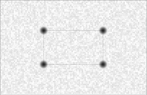
Figure A1. Example of target used for GT measurement. The markers are Gaussian blurs forming the vertices of a rectangle. The background is a low contrast texture which provides sufficient texture for on-chip and tare calibration. This target is designed with marker separations of 175mm in X and 100mm in Y, marker diameter of 30mm, and to be printed onto an 11x17” format . See Appendix A for other formats and printing instructions.
The principle of operation is simple and illustrated in Figure A2. The distance from the camera to the target on which reference marks are placed can be calculated from:
Where:
Z0 = Distance from camera to target (i.e., GT)
F = Camera focal length
XT = Target size (distance between target spot centers)
xi = Image size (corresponding separation of spots in image)
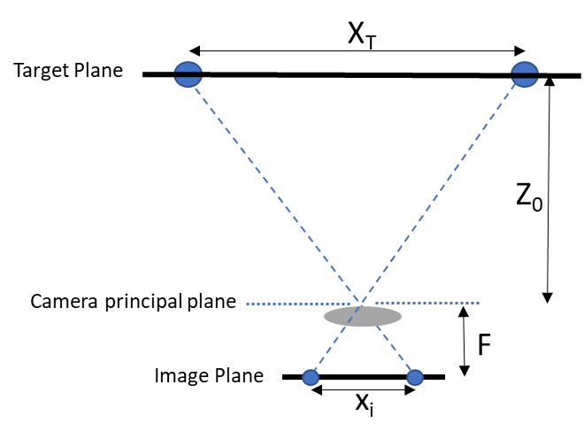
Figure A2. Principle of operation for GT measurement using two markers. GT (Z0) can be calculated from the known target size (XT), camera focal length (F), and the measured image size of the target (xi). The concept can be easily generalized to any larger number of markers.
Equation A1 can be generalized for targets with more than two spots by using the overall size of the object formed by the spots and its corresponding image size (i.e., the image magnification). In the case of the 4-point target in Figure A1, this would be the 4 sides of the rectangle and its corresponding image size. It is assumed that the camera focal length is known and scaled in pixels normalized to the resolution used to capture the images. If XT is known, then GT can be determined by accurately measuring the image coordinates of the spot centers. Clearly, the accuracy of the GT measurement is determined by the combined accuracy of each of the three factors in Equation A1 and each is discussed below.
Since the target size and focal length are fixed system parameters and, in principle, known, the GT measurement is ultimately limited by the accuracy of the measured image size derived from the (x, y) coordinates of the marker images. In practice, these need to be determined to within a fraction of a pixel for this method to provide sufficient accuracy. A variety of methods can be used to precisely determine the center of each spot image. The method used here is based on a 2D cross-correlation between the image and a Gaussian reference function. The peak of the cross-correlation for each spot is used to define the corresponding coordinates from which the image size (xi) is computed. (It is beyond the scope of this paper to compare the accuracy of the many different types of targets and algorithms. Our choice was informed by many studies of accuracies across many different real-world measurements and lighting conditions).
For an accurately measured image size, the limiting factors on GT accuracy are the target size and camera focal length. Any errors in either of these parameters directly affect the GT result in a linear manner, e.g., a 0.1% error in F or XT translate to a 0.1% error in GT.
The general flow includes:
- Calculate target Z (GT):
• Detect target spots
• Compute target rectangle side lengths
• Calculate Z in equation A1 using target side lengths and focal length. - Run Tare operation as in Section 3 using the calculated Z as GT.
Note for D455 users: The procedure above should be done with thermal loop configuration off, which is done by default when using the RS Viewer or Depth Quality Tool. See python example code referral in Appendix C.
Using Intel RealSense Viewer for GT Measurement##
The process described above for obtaining GT using a target such as the one in Figure A1 has been implemented in the RealSense SDK, Viewer, and DQT v2.50.0+ and is included as part of the Tare function since the GT value can be used as the reference distance for Tare as an alternative to manual user entry. The basic operation in the RealSense Viewer is described below and illustrated in Figure A3. The Tare function is accessed and run as described in Section 3. Once selected, the user has the option of entering a GT value or using the “Get” button to run the target-based function described above and use the measured value as GT for the Tare using the following sequence:
- Press “Get” button to display the target dimensions which can be updated with the known marker separations (in mm) in X (Width) and Y (Height);
- Place and align the camera and target to nominally frontal parallel fixed positions such that the 4 spots are inside the marked ROI;
- Press “Calculate” to initiate image acquisition and GT measurement which will be displayed;
- Press “Calibrate” to run the Tare function based on the measured GT value. Once complete, the User has the option of accepting the new calibration or keeping the original. The GT or Tare functions may be repeated as needed if results of either are unacceptable.
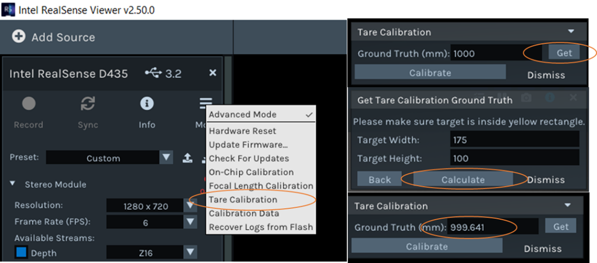
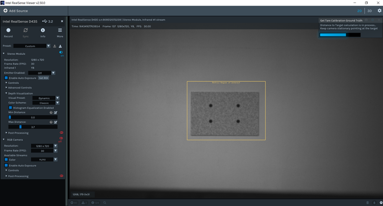
Figure A3. Operation of Tare with GT. Select Tare Calibration from the pull-down menu under More. To compute GT using a properly positioned target, select “Get” and then enter the known target dimensions (marker separations in mm). Select “Calculate” to initiate GT measurement which will typically take <3 sec. The measured GT value is displayed and used as GT for the Tare which is run in the usual manner by selecting “Calibrate”. The bottom shows an example of the RealSense Viewer UI during the GT calculation for a D435 with a well-aligned target at 1m. The left camera image with target within the ROI is displayed.
The standard target in Figure A1 is intended for use over most of the normal operating range of D4xx cameras. However, because of different FOVs, the optimal range does depend on camera model. For D435 and D455, the recommended range is ~650mm to ~1.8m and for D415 from ~950mm to ~2.5m. Operation can be extended beyond these upper limits, but accuracy will begin to degrade. At the low end of the range, the markers begin to fall outside the active ROI and will not be accurately measured. If any of the spots is not properly detected due to target misalignment or distance, an error message will be displayed (see Figure A5). For operation outside the recommended range, the target size can be scaled accordingly.
Usage Guidelines and Considerations##
When used in the recommended manner described above, target-based GT determination will provide sufficiently accurate GT for the Tare function. For an accurately measured target and camera with well-known focal length, GT errors should be less than ~0.2% (of distance) over the recommended operating range. For example, at 1m the error would be <2mm. This is on par with or better than independently measured values. Exceptions to this level of performance, sources of error, and general operational guidance is discussed below.
A. Target Considerations:
The standard target shown in Figure A1 is available in PDF format for printing onto 11 x 17” or 8 ½ x 11” format (see Appendix A). Standard, low-gloss printer paper is fine though heavy-weight stock may be more durable during attachment and subsequent usage. It is recommended to be mounted onto a flat and rigid backing material such as poster board or Gatorboard. The large format allows the target to be used over the maximum operating range, however smaller versions (e.g., 8 ½ x 11”) can be used with no compromise in performance. Also, the aspect ratio of the rectangle was chosen to closely match that of the D4xx cameras, but this may also be changed, if needed.
Target Size: While the target dimensions are designed to be specific values (175x100mm), there is variability among printers and even between prints from the same printer. As much as 0.5% variation has been observed for the same target printed on a range of standard ink jet and laser printers. It is therefore recommended that the center-to-center spot separations be measured as accurately as possible for each target and these values entered into the target dimensions window. The dashed lines between spots are provided as an aid to this step.
Target Alignment: The primary requirement on target alignment is having all four marks fully within the operational ROI in the center of the FOV shown in Figure A3. If any spots are too close to an ROI edge, an error message will be displayed. An additional requirement is that each quadrant of the ROI contain one spot, which constrains the target to near the ROI center. While the optimal target alignment is parallel to camera and near center, as shown in Figure A3, GT measurement is tolerant to x-y shift as well as slight rotation about z axis. Target tilt of about x and y axes of +/- 5 degrees will lead to a small (~0.2%) bias in the GT result and tilts up to 3 degrees are negligible if the target is well-centered. Examples of acceptable and problematic target alignments are shown in Figure A4.
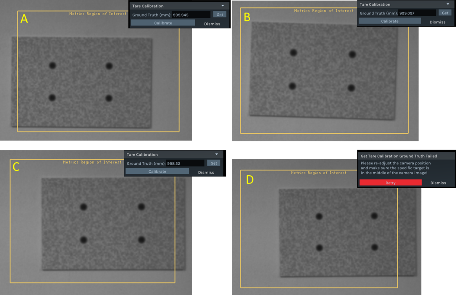
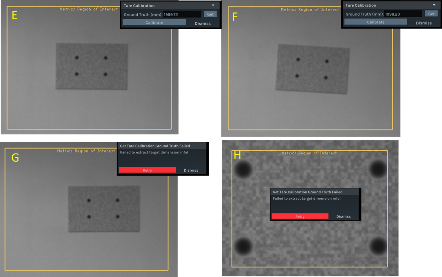
Figure A4. Examples of various target alignments with a D435. A-C: consistent and accurate results (within 2mm) for off-center and slightly rotated target at 1000mm. D: target is too far from center of ROI resulting in error message. E-F: examples of acceptable alignment at 2000mm (error < 2mm). G: target too far from center resulting in error message. H: Target centered but too close (400mm) resulting in error message due to spots too close to ROI border.
B. Ambient Lighting:
Accurate results are obtained over a wide range of ambient lighting conditions from dim indoor (~10 Lux) to moderate outdoor lighting (~10kLux). In some cases of bright ambient lighting, a target detection error results from image saturation. In such cases, the problem can be avoided by turning off AE and using a fixed exposure time . The exposure time may need to be adjusted based on the ambient lighting to avoid image saturation. The main requirement is that the illumination be reasonably uniform, in particular over the marker regions of the target. Strong lighting gradients or shadows may lead to either a faulty reading or error message and are to be avoided. A few examples are shown in Figure A5.
C. General Usage Tips:
The optimal setup is one where the camera and target are stable with target centered, parallel and uniformly illuminated with a nominal distance near 1m. Any relative movement during the GT measurement process will affect the result. Since the GT result will typically be used as the input to the Tare function, it is also important to maintain the same camera-target positions used for GT for the subsequent Tare. The full GT-Tare process will typically take <20 seconds (~12 sec for GT, ~6 sec for Tare). Alternative setups that can work include placing the target flat on the floor and pointing the camera down. A tripod or equivalent mount is recommended (see Figure A5) though holding the camera against a stable surface (e.g., edge of a table) can also work providing the camera is stable and the center ROI is clear during the GT-Tare process.
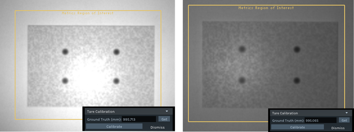
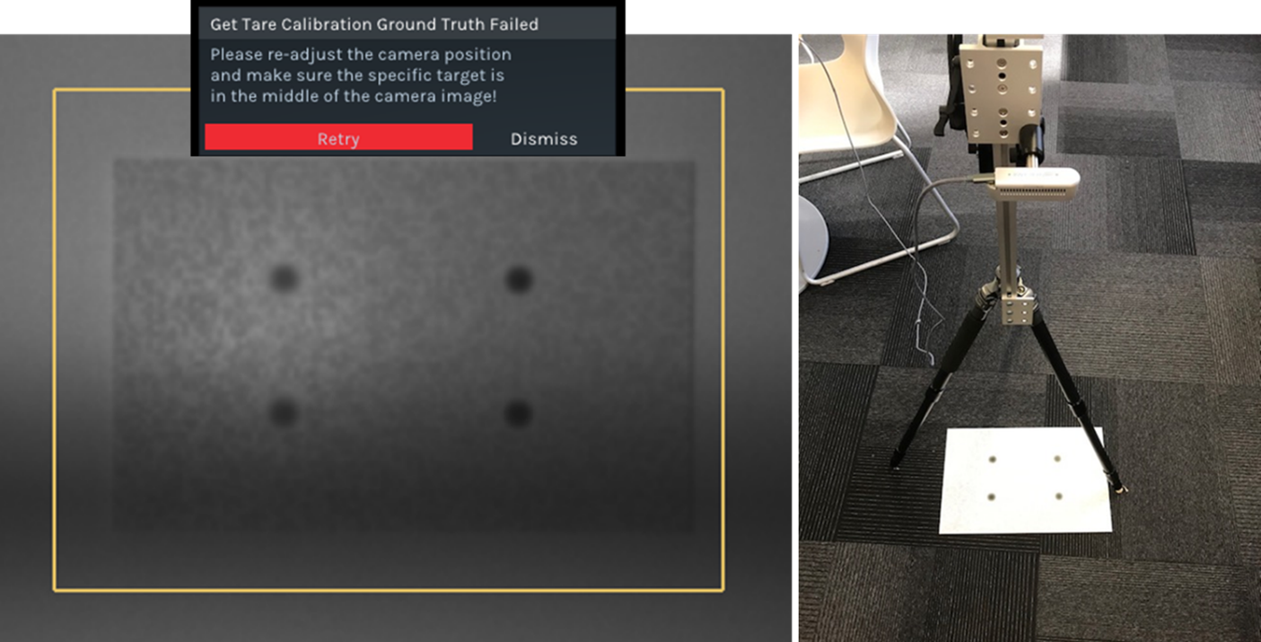
Figure A5. Examples of non-ideal lighting conditions, error message, and alternative configuration. Top: targets with non-uniform illumination (bright in center) leading to a ~0.5% error in GT result. Bottom Left: shadow over part of marker leading to error message. Failure can occur if any of the four markers is not properly detected, which can occur if target is not properly positioned or a marker is occluded. Bottom Right: Alternative arrangement with target on floor and camera mounted on tripod and facing down.
D. Sources of Error:
As described above, the accuracy of the target-based GT measurement is ultimately determined by the accuracy of the three input parameters (target size, image size, focal length). Any factors that lead to errors in any of these parameters will result in error in the GT value in the form of bias or noise.
- Target size errors are controlled by accurately measuring the marker spacing on the printed target. Errors in target size translate linearly to GT errors, e.g., a 0.1mm error in a 100mm marker separation results in 0.1% GT error. If systematic errors in GT results are observed, especially across all cameras, it is recommended to confirm the target size and adjust if needed.
- Image size errors are affected by accuracy and noise in the spot image center determination. Under optimal conditions, errors are much less than 0.1 pixel but can increase if any spots are poorly or non-uniformly illuminated, the target is severely tilted, or spot contrast or size is too small (e.g., at large distances). For example, a 0.1 pixel error in image size results in ~1mm error at 1m for a D435/455 camera and the error scales as square of distance.
- Focal length errors are controlled by the accuracy of the camera calibration. In most cases, such errors are less than ~0.3% but can be larger for cameras that have undergone significant calibration degradation due to temperature/humidity cycles or experienced mechanical shock. If GT errors are observed, especially when camera-specific, it is likely to be caused by a change in the camera’s focal length that occurred since its last factory or OEM calibration. For significant focal length-related GT errors, the recommended remedy is a new OEM calibration.
Addendum B (March 2022): Focal Length Calibration
A new feature designed to correct Left-Right camera focal length imbalance has been developed and added to the Intel RealSense SDK (LibRS v2.5.0) as well as RealSense Viewer and Depth Quality Tool. This addendum describes this new feature and its usage.
Background##
Ideally, the Left (L) and Right (R) cameras of a stereo pair have identical focal length (FL) or any small differences in the actual FLs have been accounted for in the depth calibration procedure. In either case, the result should be virtually identical image magnification for L and R cameras, which is equivalent to matching their FOVs (assuming identical sizes of L-R sensors). Matched FLs ensure uniform disparity matching across the horizontal (X) axis of the depth image and therefore a uniform depth map when viewing a planar parallel surface. Any L-R FL imbalance results in a tilted depth map and thus a Z error that varies across the image. The tilt is generally linear vs X position and depends on the FL imbalance according to the following formula:
Where:
x = Horizontal tilt angle of depth image
Z = Distance to planar target
BL = Camera baseline
R = Ratio of R/L camera FLs (the FL imbalance)
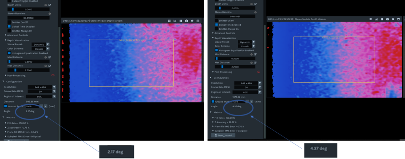
Figure B1. Example of tilted depth image due to FL imbalance. A D455 is aligned parallel to wall at a distance of (L) 1m and (R) 2m. The fitted plane is tilted at ~2.2 and ~4.4 deg, respectively, primarily in the horizontal direction. The corresponding FL imbalance (R-1) is ~0.4%.
The horizontal tilt angle is typically measured by the X-component of a plane-fit to the depth image. It is therefore important that the camera be aligned parallel to the target independent of the depth image. It is clear a ratio (R) = 1 is ideal and results in a uniform, non-tilted depth image. Note also that the tilt angle increases linearly with Z. This suggests one way to distinguish a FL imbalance from a camera that is simply tilted with respect to the target which would produce a constant tilt independent of distance. This fact also illustrates the potential problem associated with FL imbalance. Since the Z error varies across the image (i.e., a tilt) and the tilt is Z-dependent, it can lead to a depth distortion that cannot be compensated by rotating the camera. The severity of the distortion increases with the variation in depths within a scene. The basic Z-dependence of the horizontal tilt is illustrated in the Fig B1 for a D455 with a R = ~1.004, equivalent to a ~0.4% FL imbalance.
In most cameras, FL imbalance should be small enough to be ignored – any impact on the depth performance is negligible. However, under certain circumstances and with some cameras, there is the possibility for L and R cameras to undergo an asymmetric shift in FL large enough to lead to performance degradation (i.e., a tilted depth image and Z error). These are situations where the FL calibration method described below can be used to recover acceptable performance.
Target-based Focal Length Calibration##
This technique for detecting and correcting FL imbalance is direct and image-based using a reference target. In principle, the absolute FL of each camera can be obtained but typically the L-R FL ratio is sufficient for FL balancing and relaxes setup requirements.
The FL Calibration method measures the relative FL of left and right cameras (R/L ratio) using a target at a single distance. The 4-marker target with a rectangular arrangement used for GT and described in Addendum A is recommended though any equivalent 4-marker target may work. Since only the FL ratio is needed, neither the target size nor actual camera-target distance need to be known. However, for simplicity, we will assume and recommend the same target specifications described in Addendum A - 175x100mm marker spacing, 30mm width, and a 10% contrast textured background printed on either 8 ½ x 11” or 11 x 17” paper. The target is preferably mounted onto a rigid, flat substrate such as foam core or Gator board, or attached to a flat surface such a wall.
The right-left FL ratio is equal to the measured right-left rectangle side length ratio (for each of the sides), assuming the distance to target is the same for both cameras. This requirement leads to an inherent sensitivity in the measured FL ratio to horizontal tilt between camera and target. Fortunately, the target may also be used to detect and correct for this tilt. The reported FL imbalance accounts for any horizontal tilt up to at least 10 – 15 degrees. If correct target dimensions are entered, an accurate estimate of the corresponding tilt angle is also reported.
The FL correction can be applied entirely to the right focal length or split equally between both cameras’ focal lengths based on user selection. Both focal length x and y components are adjusted, and changes are applied to the camera calibration.
Upon successful target extraction and processing, which takes ~10 seconds, the algorithm yields the following metrics – the target’s plane horizontal angle with respect to the sensor’s pose, and the tilt-corrected focal length ratio.
Note for D455 users: The procedure above should be done with thermal loop configuration off, which is done by default when using the RS Viewer or Depth Quality Tool. See python example code referral in Appendix C.
Using Intel RealSense Viewer for FL Calibration##
The process described above for FL calibration using a target such as the one in Figure A1 has been implemented in the RealSense SDK, Viewer, and DQT v2.50.0+. The basic steps for operation are described below.
The Focal Length Calibration function is accessed from the More pull-down menu. Once selected, the FL Calibration window appears in the upper right of the UI and FL calibration proceeds as follows:
- Confirm or enter the correct target dimensions;
- Align the camera and target to nominally frontal parallel fixed positions such that the 4 spots are inside the marked ROI of each camera;
- Press “Calibrate” to begin the FL calibration process;
- The calibration will complete within ~10 seconds and the results will be reported. Once complete, the User has the option of accepting the new calibration (“Apply New”), keeping the original (“Dismiss”), or running the FL calibration again (“Recalibrate”). The FL Calibration may be repeated as needed if results are unacceptable.
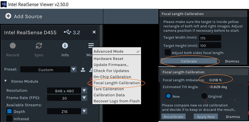
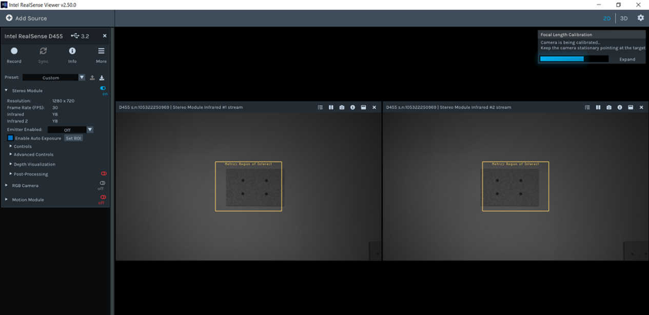
Figure B2. Operation of Focal Length Calibration. Select Focal Length Calibration from pull-down menu under More. Confirm or enter the correct target dimensions and align the camera and target such that all 4 spots are within the marked ROI on both cameras. Select “Calibrate” to initiate the FL calibration. The measured FL imbalance is displayed along with an estimate of the horizontal target tilt angle. Select “Apply New” to update the camera FLs based on the measurement or “Recalibrate” in order to repeat the measurement. The bottom shows an example of the RealSense Viewer UI during FL calibration for a D455 with a well-aligned target at ~1m. Note that the target is symmetrically placed between the Left and Right cameras.
Once FL calibration has completed, the user can toggle between the original and new calibration before deciding on whether to apply or dismiss. If the new FL values are accepted, a corresponding message is displayed, as shown in Fig B3. When performed under the recommended conditions, the FL imbalance result is generally accurate to within +/-0.03%. In most cases, a FL imbalance of up to +/-0.2% will have a negligible effect on performance and can be tolerated without correction. FL errors much larger than +/-0.2% are recommended to be corrected.

Figure B3. Sample focal length calibration result. The reported focal length imbalance is the corrected ratio for the measured set-up horizontal tilt angle. If “Apply New” is selected, a “Calibration Complete” message is displayed indicating successful updating of focal length values.
Usage Guidelines and Considerations##
• For best results, the recommended RealSense GT target with 175x100mm dimensions and textured background (used for On-chip and Tare Calibration) should be used, but targets of different size may also be printed onto matte paper and attached to wall or other flat surface. The region immediately surrounding target should be as uniform as possible.
• The exact distance to target is not critical but must be large enough to fit target in center ROI for both L and R cameras. The procedure can be made to work with recommended target between ~0.65m and ~2.0m from camera for D435/455 (recommended 0.8 - 1m) and ~0.75m and ~2.5m (recommended 1 – 1.2m) for D415. The optimum target position is symmetrically between the L and R cameras and both must see all 4 markers, as shown in Fig B2. If target is positioned too far left/right or up/down, an error message will appear.
• It is strongly recommended that camera and target be stable during the calibration process. Handheld operation, while possible, is prone to error and not recommended.
• Brightness of ambient lighting is not critical, but it is strongly recommended that illumination be uniform over target. Brightness variations, gradients, shadows, or hot spots, especially near target markers can lead to errors.
• Optimal results are obtained for target parallel to camera with minimal rotation about X, Y, and Z axes and symmetrically positioned between cameras. Some target misalignment is acceptable:
o Slight Z axis rotation is tolerated up to a point where spots are not properly detected resulting in an error message.
o FL result is insensitive to X axis rotation (vertical tilt) up to at least +/-5 deg.
o FL ratio is inherently sensitive to Y axis rotation (horizontal tilt) but this tilt angle is detected and its effect corrected in the reported FL imbalance, as described above. Angles up to at least +/-10 deg are correctable, but it is recommended to minimize tilt as much as possible.
o Exact X-Y target position is not critical as long as spots are within marked ROI and not too close to edge or center.
Some examples of acceptable and unacceptable target alignment are illustrated in Fig B4 and B5.
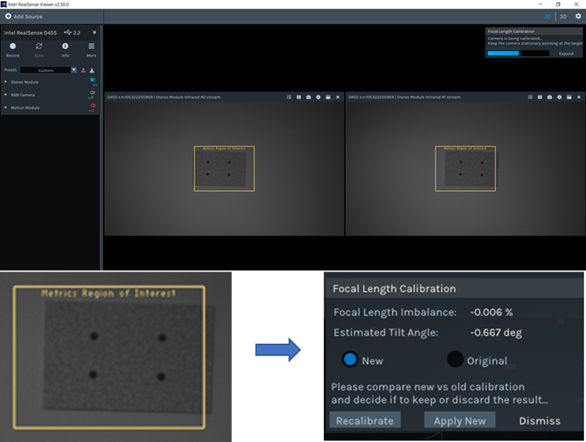
Figure B4. Slight rotation of target about Z axis is acceptable. The Left camera image and corresponding successful FL measurement is shown.
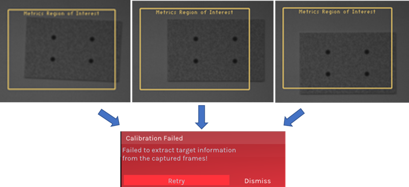
Figure B5. Examples of unacceptable target alignment. The Left camera image is shown for excessive Z-rotation (Left), target shifted too far right (Center), and target shifted too far down (Right). The corresponding error message is shown below.
Appendix
Appendix A: Example Textured Target
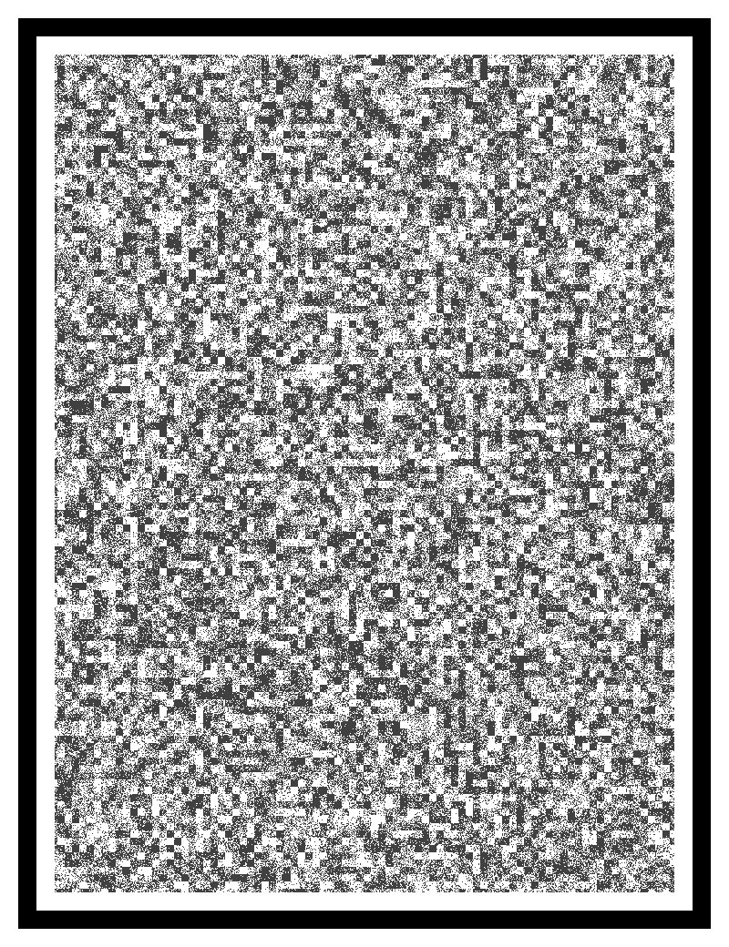
Appendix A: Example printable target.
Ground-Truth Targets and Printing & Mounting Instructions###
- GaussianBlur30x100x175back-11x17-A3.pdf
- GaussianBlur30x100x175back-8.5x11.pdf
- GaussianBlur30x100x100back-8.5x11.pdf
Included here are three versions of the ground-truth target, designed for printing onto standard 8 ½ x 11” or 11 x 17” paper. In all cases, it is recommended to print with no scaling (i.e., 100% zoom) onto matte (low-gloss) heavy-weight stock paper for higher durability during attachment and subsequent usage though standard printer paper is also acceptable.
It is recommended to mount target onto a flat and rigid backing material such as poster board or Gatorboard for portability though attachment flush to a flat wall is also acceptable. The large format allows the target to be used along with Tare over a larger operating range, however smaller versions (e.g., 8 ½ x 11”) can be used with no compromise in performance.
The included targets are designed to be 175 x 100 mm or 100mm x 100mm but careful measurement of the actual dimensions (center-to-center marker spacing) is recommended. Target sizes may be modified, as needed, as long as the printing, mounting, and size confirmation guidelines are followed.
Appendix B: Details on Self-Calibration Flow and C API:##
B. Recommended calibration flow for D400 series:
o Print GT target and fasten it flattened to a wall – required only for focal length calibration and GT calculation, but can be good target for OCC and tare as well.
o Place the camera perpendicular to the target, such that target will appear in the center of camera FOV.
o Verify that camera – target tilts are minimized (see Addendum A). You can use DQT to measure and establish the tilt angles.
o Camera - target distance should follow the recommendation given in this white paper.
o Verify that camera is functional – Depth, IR1, IR2 and RGB can stream. In case you use D455, make sure to switch off thermal loop control.
o Run on-chip calibration (no need to set specific stream).
o Prepare stream for Focal calibration function: Set resolution 1280x720, format Y8L Y8R, fps can be anything from the supported list according to USB connection. See Errata about USB2 for d455 and d415.
o Write the on-chip calibration result to memory.
o Measure accurate target dimension and provide it to focal length calibration function. (this phase is needed for focal calibration and Ground Truth calculation).
o Run Focal length calibration.
o Write the focal length calibration result to memory.
o Prepare stream for Ground Truth calculation function: Set resolution 1280x720, format Y8L, fps can be anything from the supported list according USB connection.
o Run Ground Truth calculation. (Use measured target dimension for input)
o Use calculated distance as input tare function.
o Run Tare calibration (no need to set specific stream).
o Write the tare calibration result to memory.
C. Running on-chip calibration:
const rs2_raw_data_buffer* rs2_run_on_chip_calibration(rs2_device* device, const void* json_content, int content_size, float* health, rs2_update_progress_callback_ptr callback, void* client_data, int timeout_ms, rs2_error** error);
This starts on-chip calibration. This is a blocking API that will return with success, failure, or timeout. When successful, the new calibration table object will be returned. When failing, an exception will be raised via standard rs2_error protocol. Exceptions can be 1. edge too close, 2. not enough fill rate, no converge, 3. device disconnected, 4. protocol error, 5. not supported, or 6. timeout.
The content of the return rs2_raw_data_buffer object can be accessed via existing rs2_get_raw_data_size and rs2_get_raw_data APIs (for example if the user wants to save calibration results to disk). It should be deleted using rs2_delete_raw_data. In order to toggle between different calibration, the pointer returned from the rs2_get_raw_data can be passed as input argument to the function call rs2_set_calibration_table. Finally, in order to “burn” the new calibration persistently to memory, the rs2_write_calibration function needs to be called.
The returned health is a signed value indicating the calibration health.
The timeout_ms is 15000 msec by default and should be set to longer than the expected calibration time as indicated in this document.
rs2_update_progress_callback_ptr and client_data are optional call-backs and can be set to zero.
The json_content and content_size are the calibration parameters passed in JSON format. Content size is the json string size in bytes.
The JSON format is for example:
{
        "calib type": 0,
	 "speed": 2,
        "scan parameter": 0,
        "white wall mode": 0
       }
Passing NULL to json_content or 0 to content_size will run the calibration with default recommended settings.
The calib_type is 0 for OCC (default),1 for OCC focal length, and 2 for OCC extended.
The speed can be one of the following values: Very fast = 0, Fast = 1, Medium = 2, Slow = 3, White wall = 4, default is Slow.
The scan_parameter is 0 for Intrinsic calibration correction (default) or 1 for extrinsic correction.
The white_wall_mode is 0 for normal mode (default), or 1 for white wall mode.
D. Running tare calibration:
const rs2_raw_data_buffer* rs2_run_tare_calibration(rs2_device* dev, float ground_truth_mm, const void* json_content, int content_size, rs2_update_progress_callback_ptr callback, void* client_data, int timeout_ms, rs2_error** error);
Similar to on-chip calibration. This will adjust camera calibration to correct the absolute distance to the flat target. User needs to enter the known ground truth to a flat target that is the size of zoomed field of view (256x144).
The ground_truth_mm is the ground truth in millimeters in range 2500mm to 2000000mm.
The json content contains the configuration parameters, but we recommend setting json_content to null, and set content_size to 0, so that default parameters are applied.
The json string is:
{
"average_step_count": 20,
"step_count": 20,
"accuracy": 2,
"scan_parameter": 0,
"data_sampling": 0
}
The average_step_count is the number of frames (from 1-30) that are averaged to improve the noise.
The step_count is the max iteration steps (between 5 and 30) that are used in the optimization search. Usually a solution is found within 10 steps.
The accuracy is the subpixel accuracy level, and the value can be one of: Very high = 0 (0.025%), High = 1 (0.05%), Medium = 2 (0.1%), Low = 3 (0.2%), Default = Very high (0.025%).
The scan_parameter is 0 for Intrinsic calibration correction (default) or 1 for extrinsic correction.
The data_sampling default is 0 which uses a polling approach that works on Windows and Linux.
The optional callback and client_data can both be set to zero. The timeout default is 5000ms.
E. Running Focal Length calibration:
const rs2_raw_data_buffer* rs2_run_focal_length_calibration (rs2_device* dev, rs2_frame_queue* left_queue, rs2_frame_queue* right_queue, float target_width, float target_height, int adjust_both_sides, float* ratio, float* angle, rs2_update_progress_callback_ptr callback, void* client_data, rs2_error** error);
This is a calibration recalculating blocking call that finds and extracts the target features, and then recalculates the sensor focal length.
The API uses a different paradigm from On-Chip and Tare calibrations in the sense that it requires the user to perform the data in two distinct phases. First, the user is required to allocate rs2_frame_queue objects and collect a specific number of frames with a predefined resolution and formats. In phase two the above API call is made that transfers the gathered data, along with the target dimensions (mm) and the flags that instructs the algorithm to rectify the focal length for either left or both stereo sensors.
While the algorithm performs the internal processing (~15-30 sec) the overall progress in [0.100] % range can be retrieved using user callback.
Upon successful target extraction and processing the algorithm yields the following metrics – the target’s plane angle w.r.t. to the sensor’s pose, and the focal length ratio correction factor.
The required resolution and format are 1280X720 and Y8 (Intensity). The number of frames to be collected is more than 10 (~30 synchronized Left/Right IR frame pairs is recommended).
The focal length calibration provides an alternative API call that is more suited for C++ usage
const rs2_raw_data_buffer* rs2_run_focal_length_calibration(rs2_device* device, rs2_frame_queue* left_queue, rs2_frame_queue* right_queue, float target_width, float target_height, int adjust_both_sides, float* ratio, float* angle, rs2_update_progress_callback_ptr callback, void* client_data, rs2_error** error);
F. Ground Truth calculation
As part of Tare calibration enhancement, a new method that uses a predefined printed target is devised that allows to calculate the range to the target’s plane.
The algorithm is performed in two stages like the Focal Length calibration elaborated above:
- Collect raw stream data (20-30 per stream)
- Process the data, extract the target’s features, and convert it to the range (mm).
Note that the accuracy of the algorithm is dependent on the target measurements performed by the user. Injecting invalid target dimensions will invalidate the calculated results, and hence may skew the calibration results.
float rs2_calculate_target_z(rs2_device* device, rs2_frame_queue* queue1, rs2_frame_queue* queue2, rs2_frame_queue* queue3, float target_width, float target_height, rs2_update_progress_callback_ptr progress_callback, void* client_data, rs2_error** error);
The input parameters queue1, queue2, queue2 shall be used to collect the input frames required by the algorithm to run, however only queue1 is utilized in the SDK v2.50 version. The additional parameters queue2, queue2 are introduced for future enhancements, so while the user is required to define those parameters, they can be empty when invoking the API call.
Target-based Ground Truth calculation is incorporated into RealSense-Viewer application and is exposed and offered as part of Tare calibration.
G. Reset calibration:
There are three ways to reset calibration.
A. After a self-calibration or Tare, the calibration is only stored temporarily in the camera. Stopping and restarting streaming reverts to the previous calibration state. Also, disconnecting the camera and restarting will also reset the calibration.
B. One can call the rs2_get_calibration_table before each tare- or self-calibration run. That way it is always possible to revert to the previous calibration using the rs2_set_calibration_table and rs2_write_calibration_table.
C. It is possible to restore to factory calibration, which is permanently stored in the camera after factory calibration.
void rs2_reset_to_factory_calibration(const rs2_device* device, rs2_error** e);
Appendix C: On-chip calibration Python API:
H. Preparing for calibration:
Starting the pipeline into a mode compatible with on-chip calibration can be done as follows:
import pyrealsense2 as rs2
pipe = rs2.pipeline()
cfg = rs2.config()
cfg.enable_stream(rs2.stream.depth, 256, 144, rs2.format.z16, 90)
dev = pipe.start(cfg).get_device()
Once started successfully, dev object can be casted to rs2.auto_calibrated_device by calling:
cal = rs2.auto_calibrated_device(dev)
I. Running On-Chip calibration:
rs2.auto_calibrated_device class allows to invoke on-chip calibration using the following blocking call:
def cb(progress):
    print(“.”)
res, health = cal.run_on_chip_calibration(timeout_ms, json, cb)
This method has similar signature and behavior to C API rs2_run_on_chip_calibration.
J. Running Tare calibration:
rs2::auto_calibrated_device class allows to invoke tare calibration using the following blocking call:
res = cal.run_tare_calibration(ground_thruth, timeout_ms, json, cb)
This method has similar signature and behavior to C API rs2_run_tare_calibration.
K. Running Focal Length calibration:
rs2::auto_calibrated_device class allows to invoke focal length calibration using the following blocking call:
res = cal.run_focal_length_calibration (left_stream_queue, right_stream_queue, target_width_mm, target_height_mm, adjust_both_sides, &corrected_ratio, &target_tilt_angle, cb)
Note for users – once a sufficient number of frames for left and right queues is collected it is advised to stop pushing additional frames into those queues.
This method has similar signature and behavior to C API rs2_run_focal_length_calibration_cpp
L. Calculating Ground Truth
rs2::auto_calibrated_device class allows to invoke focal length calibration using the following blocking call:
res = cal.calculate_target_z(frame_queue1, frame_queue2, frame_queue3, cb)
User note – frame_queue1 expects Y8 stream format with 1280X720 resolution. The additional two frame queues (frame_queue2, frame_queue3) are provisional for future improvements and currently may be passed into the API call empty-handed
This method has similar signature and behavior to C API rs2_calculate_target_z
M. Setting / Resetting the calibration:
Assuming calibration completed successfully, new calibration table can be applied to the current streaming session using cal.set_calibration_table(res)
Saving new calibration permanently to the device can be done via cal.write_calibration() after calling set_calibration_table. It is also possible to reset the device to its factory calibration using cal.reset_to_factory_calibration()
Please see depth_auto_calibration_example.py under wrappers/python/examples.
Appendix D: On-chip calibration C++ API:
N. Preparing for calibration:
Starting the pipeline into a mode compatible with on-chip calibration can be done as follows:
rs2::pipeline pipe;
rs2::config cfg;
cfg.enable_stream(RS2_STREAM_DEPTH, 256, 144, RS2_FORMAT_Z16, 90);
rs2::device dev = pipe.start(cfg).get_device();
Once started successfully, dev object can be casted to rs2::auto_calibrated_device by calling:
rs2::auto_calibrated_device cal = dev.as<rs2::auto_calibrated_device>();
O. Running On-Chip calibration:
rs2::auto_calibrated_device class allows to invoke on-chip calibration using the following blocking call:
float health;
rs2::calibration_table res = cal.run_on_chip_calibration(json, &health, [&](const float progress) { /* On Progress */ });
This method has similar signature and behavior to C API rs2_run_on_chip_calibration
However, unlike its C counterpart, it receives JSON parameters via C++ std::string, can use C++ 11 anonymous function as the progress callback (as well as regular function pointer) and returns object of type rs2::calibration_table that does not require explicit deinitialization. In case of an error, this API will throw an exception of type rs2::error.
P. Running Tare calibration:
rs2::auto_calibrated_device class allows to invoke tare calibration using the following blocking call:
rs2::calibration_table res = cal.run_tare_calibration(ground_thruth, json, [&](const float progress) { /* On Progress */ });
This method has similar signature and behavior to C API rs2_run_tare_calibration with same notes from the previous section apply.
Q. Running Focal Length calibration:
rs2::auto_calibrated_device class allows to invoke focal length calibration using the following blocking call:
auto cal = dev.as<auto_calibrated_device>();
new_calib = cal.run_focal_length_calibration(left, right, target_width_mm, target_height_mm, adjust_both_sides, &corrected_ratio, &target_tilt_angle, callback);
Implementation notes:
– The left/right frame queues shall be allocated and prepared in the user application
– after collecting the required number of frames for for left and right queues, it is advised to stop
This method has similar signature and behavior to C API rs2_run_focal_length_calibration_cpp
R. Calculating Ground Truth
rs2::auto_calibrated_device class allows to invoke focal length calibration using the following blocking call:
auto cal = dev.as<auto_calibrated_device>();
res = cal.calculate_target_z(frame_queue1, frame_queue2, frame_queue3, callback)
User note – frame_queue1 expects Y8 stream format with 1280X720 resolution. The additional two frame queues (frame_queue2, frame_queue3) are provisional for future improvements and currently may be passed into the API call empty-handed
This method has similar signature and behavior to C API rs2_calculate_target_z
S. Setting / Resetting the calibration:
Assuming calibration completed successfully, new calibration table can be applied to the current streaming session using cal.set_calibration_table(res);
Saving new calibration permanently to the device can be done via cal.write_calibration(); after calling set_calibration_table. It is also possible to reset the device to its factory calibration using cal.reset_to_factory_calibration();
Appendix E: Self-calibration with LabVIEW.
A new “Hello World” example VI was added, that shows how to implement Self-Calibration and Tare in LabView. A few new sub-VIs were added. Note also that the user is guided to be in 256x144 resolution mode.
RS3_Get_Calibration_Table.vi: Call this first to get a pointer to the existing calibration table.
RS3_Run_OnChip_Calibration.vi: Run the self-calibration and return the Health-Check number and a pointer to the new calibration table.
RS3_Get_Raw_Datasize.vi and RS3_Get_Raw_data.vi: Use these to update the calibration table, and allow the user to toggle between the old and new calibration table.
RS3_Run_OnChip_Tare.vi: Run the tare calibration and return pointer to new calibration table.
RS3_Burn_Calibration_table.vi: Write new calibration table permanently to ASIC.
RS3_reset_Calibration_table_to_Factory.vi: Allows to recover to the original factory calibration stored in ASIC.
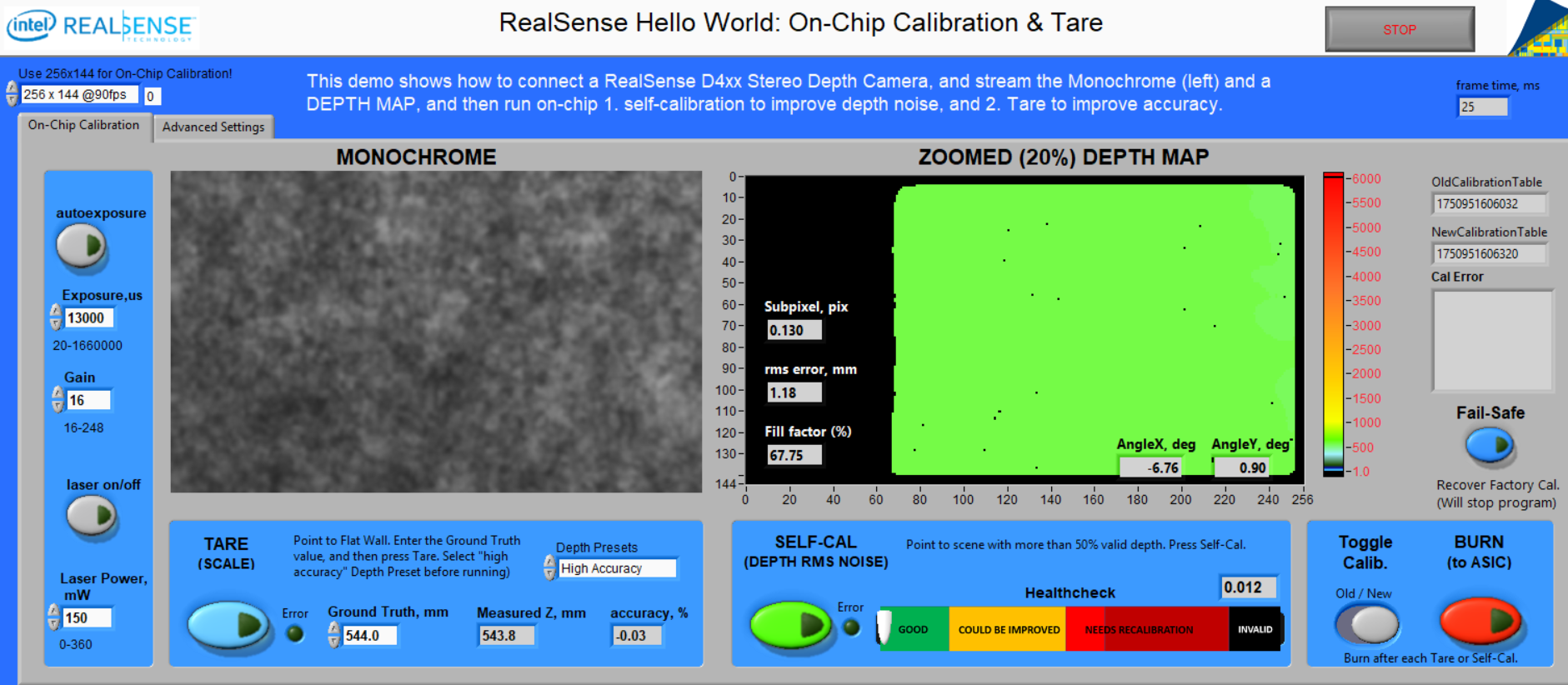
Fig 12: Hello World: On-Chip Calibration & Tare
Updated about 1 year ago