Depth image compression by colorization for Intel® RealSense™ Depth Cameras
Authors: Tetsuri Sonoda, Anders Grunnet-Jepsen
Rev 1.0
This article is also available in PDF format

Fig. 1 Left: Original depth image of D435. Center: Colorized depth image with JPG compression. Right: Recovered depth image from colorized and JPG compressed depth
Compression of RGB images is today a relatively mature field with many impressive codecs available to choose from that can achieve high compression ratios for lossless and lossy compression. However, for 3D depth images, the field is not as developed, although the goal remains the same – to compress both still- and moving- images in order to reduce system bandwidth and storage space requirements. In this white paper, we introduce a method by which depth from Intel RealSense depth cameras can be compressed using standard codecs, with the potential for 80x compression. Our approach is based on colorizing the depth image in a way that best reduces depth compression artefacts. We will define some key performance metrics, compare results obtained with different compression codecs, and introduce a post-processing technique that helps mitigate some of the worst depth artefacts.
1. Introduction
The Intel RealSense Depth Camera, D400 series can output high-resolution depth image up to 1280 x 720 with 16-bit depth resolution [1]. In order to efficiently store such high-resolution images in a limited disk space or to minimize the transmission bandwidth, an appropriate compression technique is required. Several novel compression techniques have been suggested in literature, and good performance can indeed be achieved, for example, by approximating a depth value by a plane divided by a quad tree [2]. However, when such unique algorithms are used, it necessitates custom proprietary software for compression and decompression, and it tends to not be able to leverage hardware acceleration blocks that already exist on many compute platforms.
In this paper, we propose a simple colorization method for depth images. By appropriately colorizing the depth image, the depth image can subsequently be treated as a normal RGB image which can easily be compressed, stored, and transmitted using widely available HW and software tools. We will describe this approach in more detail below, where we will cover 1. the colorization and recovery methods, 2. an application example of compression using a lossy image codec, and 3. various considerations that need to be made to ensure optimal results.
2. Depth image colorization
Intel RealSense D400 and SR300 series depth cameras output depth with 16-bit precision. We can convert this to an RGB 24 bits color image by colorization, but the exact mapping can be very important. We recommend using the Hue color space, as shown in Figure 2, for conversion from depth to the color image. This Hue color space has 6 gradations in the up and down directions of R, G, and B, and has 1529 discrete levels, or about 10.5 bits. Furthermore, since one of the colors is always 255, the image never becomes too dark. This has the benefit of ensuring that details are not lost by some of the lossy compression schemes described later.

Fig. 2 Hue color bar used to map depth to color
2.1 Uniform colorization and inverse colorization
The proposed colorization process imposes the limitation of needing to fit a 16-bit depth map into a 10.5-bit color image. We recommend performing the colorization only after first limiting the depth range to a subset of the full depth 0 ~ 65535 range, and re-normalizing it. The depth range can, for example, be determined by windowing it to between a minimum depth value dmin and a maximum depth value dmax. The greater the depth range, the coarser the quantization of the depth value becomes. There are two methods for this colorization: uniform colorization which directly converts the depth value, and inverse colorization which converts the disparity value (which is the reciprocal of the depth value). Uniform colorization quantizes the entire depth range uniformly. In inverse color colorization, quantization is finer at closer depths and coarser at longer depths. Inverse colorization is particularly well suited to depth cameras, like the D400 series, that derive depth from triangulation, which inherently has an inverse relationship between resolution and distance away.
The colorization proceeds as follows: Each color of the uniformly colorized pixel pr, pg and pb should be determined by the following equation, where the input depth value of the target depth image is d.
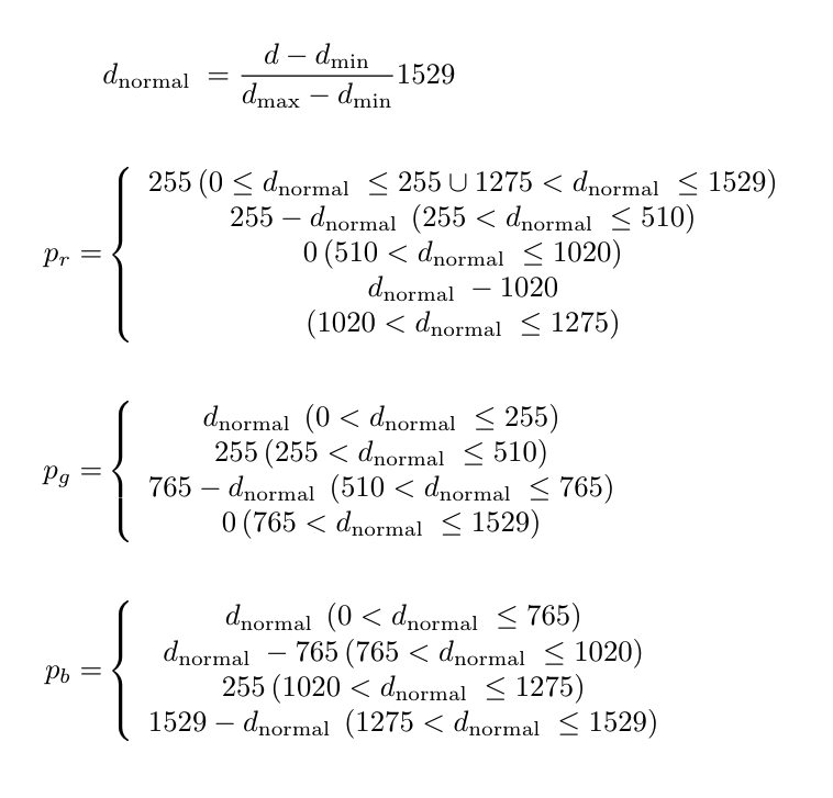
Equation 1
Alternatively, when using the depth disparity map, the with disparity values, disp, the dnormal above is replaced by the following equation:
Equation 2

Fig. 3 Left: Uniformly colorized depth image. Right: Inverse colorized depth image
By performing the above conversion on all pixels, it is possible to colorize the target depth image, as shown in Figure 3 for each approach. Lossless or lossy compression for RGB images can now be applied to these colorized depth images, allowing them to be stored in smaller files and transmitted over the network with lower bandwidth.
2.2 Depth image recovery from colorized depth image
To use a colorized depth image after it has been compressed, stored/transmitted, and then uncompressed, it must be converted back to a depth map image. Each color of each pixel p of the colorized depth image is represented by prr, prg, and prb, and the restored depth value drecovery of the pixel can then be obtained by the equation below. When restoring the depth map, the shortest depth dmin and the longest depth dmax used for colorization the depth image are required as input parameters.
Equation 3
For inverse colorized depth images, the recovered depth value drecovery of the pixel pr is expressed by the following equation:
Equation 4

Fig. 4 Left: Point cloud using depth image recovered from uniformly colorized depth image.
Right: Point cloud using depth image recovered from inverse colorized depth image.
Depth range is set to 0.3-16m
By performing the above conversion for all pixels, the depth image can be recovered, as shown in Figure 4. The image quality improvement of using disparity instead of depth, i.e. the inverse colorized depth, is clearly evident in Figure 4, for objects that are near. The recovered depth values appear to be more quantized when using the uniformly colorize approach, however, results can be improved dramatically if the uniform depth range is limited to say, 0.3m to 2m.
This depth image restoration is in principle independent of whether a lossless compression is used, such as PNG, or a lossy compression is used, such as JPG and MP4 etc. However, when recovering depth after lossy compression, it is very common to see “flying pixels” generated at the boundary of discontinuous depth values. In this case removal by post-processing will be required.
In the following section we will go into more details about how we have integrated colorization and recovery into the Intel RealSense SDK 2.0, and also how post-processing of depth images can be used to minimize the flying pixel artefacts.
3. How to colorize depth images and recover colorized depth images in C++
We describe here an examples of C++ programs for colorizing a depth image and for restoring a depth value from the colorized depth image. Colorizing of depth images is implemented as a post-processing filter in the Intel RealSense SDK 2.0 [3] and can be easily enabled. Figure 5 shows the Intel RealSense Viewer and the controls under Depth Visualization for selecting HUE and the min and max distance.
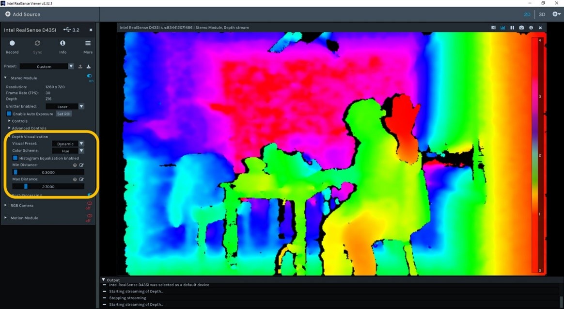
Fig. 5 The Intel RealSense Viewer showing how to select HUE color scheme for visualization, as well as range defined by dmin and dmax.
The colorization, compression (by JPG) and recovery example project using OpenCV [4] can be downloaded from [5].
3.1 Colorize depth images in C++ with the Intel RealSense SDK 2.0
Colorization is enabled with the following C++ code. The Colorization function is implemented as an SDK post-processing filter and is applied to the frame obtained from the pipeline.
bool is_disparity = false;

// pipeline start
rs2::pipeline pipe;
pipe.start();

// declare filteres
rs2::threshold_filter thr_filter;	// Threshold - removes values outside recommended range
rs2::colorizer color_filter;	// Colorize - convert from depth to RGB color
rs2::disparity_transform depth_to_disparity(true);	// Converting depth to disparity

rs2::frameset frames = pipe.wait_for_frames(); // Wait for next set of frames from the camera
rs2::frame filtered; //Take the depth frame from the frameset

// apply post processing filters
filtered = frames.get_depth_frame();
filtered = thr_filter.process(filtered);
filtered = depth_to_disparity.process(filtered);
if (!is_disparity) { filtered = disparity_to_depth.process(filtered); }
filtered = color_filter.process(filtered);
is_disparity is a flag for switching between uniform colorization and inverse colorization, and when true, inverse colorization is performed using the disparity value. The following codes are used to specify the minimum depth, maximum depth, and colorization mode required for colorization.
float min_depth = 0.29f;
float max_depth = 10.0f;

// filter settings
thr_filter.set_option(RS2_OPTION_MIN_DEPTH, min_depth);
thr_filter.set_option(RS2_OPTION_MAX_DEPTH, max_depth);
color_filter.set_option(RS2_OPTION_HISTOGRAM_EQUALIZATION_ENABLED, 0);
color_filter.set_option(RS2_OPTION_COLOR_SCHEME, 9.0f);		// Hue colorization
color_filter.set_option(RS2_OPTION_MAX_DEPTH, max_depth);
color_filter.set_option(RS2_OPTION_MIN_DEPTH, min_depth);
As described above, when the depth range is set to the minimum range to be used, the quantization error can be reduced in both uniform colorization and inverse colorization. On the other hand, in the case where the lossy compression is applied, it turns out it is necessary to allow a margin in the depth range to be larger than the actual used range in order to prevent inversion of the depth value as described later. Note that the Hue color scheme has more quantization levels than other color schemes implemented in Intel RealSense SDK.
3.2 Depth image recovery from colorized depth images in C++
The ability to recover colorized depth images is not currently available in the Intel RealSense SDK 2.0. This is because if a depth image is stored in a file or data is transmitted through a network is to be recovered, the depth camera may not be directly connected. For this reason, we created instead a stand-alone code example to recover the depth, that can be used independent of the SDK.
Input: unsigned char input_color_data_array RGB 8bit x 3 colorized depth image
Output: unsigned short output_depth_data_array 16bit depth image
// resolution is set to 848 x 480
int _width = 848;
int _height = 480;
bool is_disparity = false;
float min_depth = 0.29f; // to avoid depth inversion, it’s offset from 0.3 to 0.29. Please see Figure 7
float max_depth = 10.0f;
float min_disparity = 1.0f / max_depth;
float max_disparity = 1.0f / min_depth;

unsigned short hue_value = 0; // from 0 to 255 * 6 - 1 = 0-1529 by Hue colorization
unsigned char* in = reinterpret_cast<const unsigned char*>input_color_data_array;
unsigned short* out = reinterpret_cast<unsigned short*>output_depth_data_array;

for (int i = 0; i < _height; i++)
{
	for (int j = 0; j < _width; j++)
	{
		unsigned char R = *in++;
		unsigned char G = *in++;
		unsigned char B = *in++;

		unsigned short hue_value = RGBtoD(R, G, B);

		if(out_value > 0)
		{
			if(!is_disparity)
			{
				unsigned short z_value = static_cast<unsigned short>((min_depth + (max_depth - min_depth) * hue_value / 1529.0f) + 0.5f);
				out++ = z_value;
			}
			else
			{
				float disp_value = min_disparity + (max_disparity - min_disparity) * out_value / 1529.0f;
				*out++ = static_cast<unsigned short>((1.0f / disp_value) / depth_units + 0.5f);
			}
		}
		else
		{
			*out++ = 0;
		}
	}
}

unsigned short RGBtoD(unsigned char r, unsigned char g, unsigned char b)
{
	// conversion from RGB color to quantized depth value
	if (b + g + r < 255)
	{
		return 0;
	}
	else if (r >= g && r >= b)
	{
		if (g >= b)
		{
			return g - b;
		}
		else
		{
			return (g - b) + 1529;
		}
	}
	else if (g >= r && g >= b)
	{
		return b - r + 510;
	}
	else if (b >= g && b >= r)
{
		return r - g + 1020;
	}
}
It is important that the values of min_depth and max_depth should be the same as those used for colorization. Of course, if the same logic as described above is applied, restoration can be performed in an environment other than C++. Also, since each pixel can be calculated independently of other pixels, processing lends itself well to acceleration via multi-threading or GPU.
3.3 Flying Pixels
As described above, when a depth image is restored from a compressed RGB image such as JPG or MP4, flying pixels may appear at the boundaries of discontinuous depth values, i.e. edges or near occlusions, as shown in Figure 6. The flying pixels tend to show up as a spray of intermediate depth values between the front and back surfaces. Such flying pixels are not readily evident on depth maps, but they are clearly visible when the depth is viewed as a point cloud and rotated 90 degrees to show the side-view. These flying pixels can be reduced by applying a post-processing filter.
The rs-colorize sample code [5] reduces flying pixels by using a modified median filter (function name: PostProcessingMedianFilter) to exclude pixels having a difference greater than a certain value between the nearest neighbor and the median value. Other methods include removing a depth value having an extreme depth slope (derivative) with respect to surrounding pixels or removing pixels that fall adjacent to pixels that do not have a depth value (i.e. next to a depth-map “hole”). When these filters are applied, the tradeoff is that the removal of pixels also reduces the depth fill-factor and increases the size of depth “holes”. In order to recover some pixels, an additional dilate process can be performed that fills holes with the median value of all adjacent pixels, for example. However, since this type of simple hole-filling algorithm may lead to false depth values, it is usually better to live with the fewer good pixels, than to dilate and possibly end up with an accurate depth map.
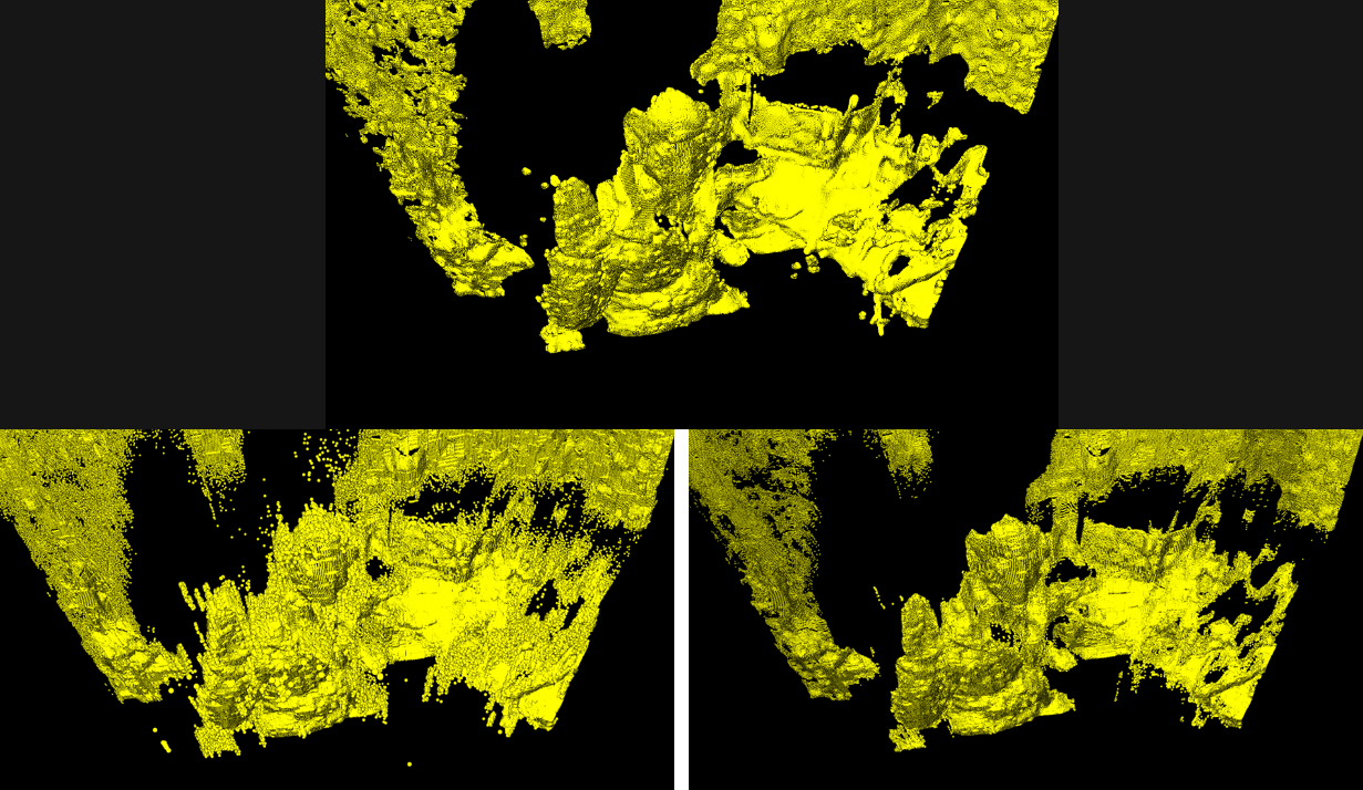
Fig. 6 These point cloud pictures show the appearance of “Flying pixels” after compression/decompression, and how they can be filtered. Top: Point cloud using uncompressed original depth. Bottom Left: Point cloud using depth recovered from JPG without modified median filter, showing the appearance of flying pixels near edges. Bottom Right: Point cloud using depth recovered from JPG with modified median filter. JPG image quality is set to 80. This final image looks very similar to the original image, with the median filter also serving to clean up the depth map and remove flying pixels.
There is yet another artefact that needs to be considered. When the depth value exists in the vicinity of the nearest depth or the farthest depth and lossy compression is applied, inversion of the nearest depth and the farthest depth may occur, as shown in Figure 7. Such inversion can be easily avoided by increasing the depth range (i.e. reducing dmin and increasing dmax) to add a margin with respect to the actual nearest depth and the farthest depth.
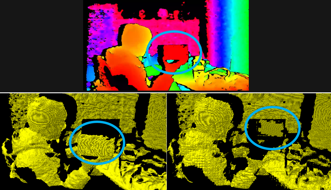
Fig. 7 Example of the “depth-inversion” artefact. Top: Colorized depth image. The box on the hand is very close to the nearest depth = red color. Bottom left: Point cloud using original depth. The box is correctly displayed on the hand. Bottom right: Point cloud using depth recovered from WebP (image quality is set to 5). The box on the hand is incorrectly displayed at the furthest depth.
4. Compression using image codecs
In order to examine further the effects of applying lossy compression to colorized depth images, a series of measurements were taken to evaluate the depth quality as a function of compression ratio and compression codec, comparing JPG and WebP.
We start by defining the image quality index as the peak-signal-to-noise-ratio, in decibels. This PSNR is a common metric used to compare the image quality of original and compressed images. The higher the PSNR the better the quality of the reconstructed image. We also compare before and after images based on fill-factor, the ratio of valid (non-zero) depth pixels to total number of pixels. A 100% fill-factor means that there are no pixels with undefined depth values.
In the following PSNR comparison, we employ the direct uniform colorization approach. This is because, for inverse colorization, the quantization error of the depth increases quadratically as the depth increases, so we would need a different image quality metric. Also, since the PSNR value is strongly affected by flying pixels, its value depends very strongly on the scene, where images with many edges and discontinuities will show much poorer performance. As a result, the PSNR metric should be used to compare the relative performance under the same conditions (i.e. same images), but it is not well suited to evaluate the generalized performance.
We compared JPG and WebP lossy image compression codecs. The depth range was set to 0.5m to 2m using the uniform colorization scheme. This ensured that 1mm depth steps could be represented without error by the 1529 available levels. Both codecs allow for adjusting the compression ratio by changing an image quality parameter. WebP has a lossless compression mode, but it was not used here.
Figure 8 shows a plot of the PSNR as a function of the compression ratio. The PSNR is evaluated only in the portion where the depth value exists in both “before” and “after” depth images.
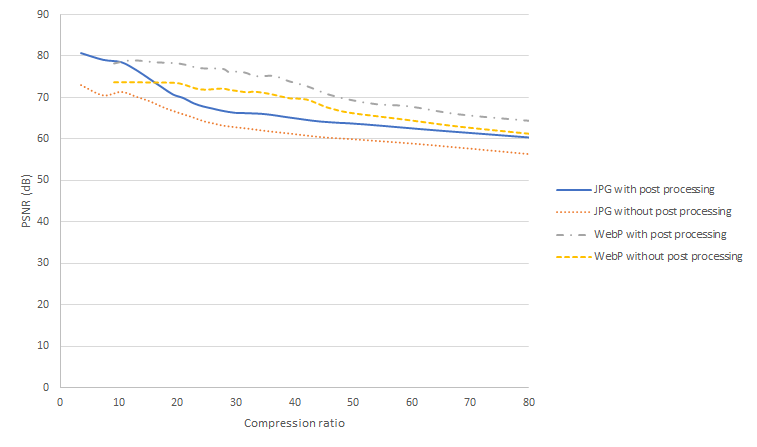
Fig. 8 Compression ratio vs PSNR of colorized depth image using JPG and WebP
For low compression ratios, up to 10x, JPG delivers a good PSNR of over 70dB. (WebP does not allow lower compression ratios). WebP delivers better results at compression ratios above 10x, with PSNR staying above 70dB for up to 40x compression, for the test scene used. By comparison JPEG drops below 70dB above 15x compression. For both codecs, removing flying pixels with post-processing improves the PSNR significantly, with JPEG experiencing a boost of almost 10dB for low compression ratios, while WebP improves about 6dB up to 40x compression.
However, post processing does have a direct impact on the fill factor as is shown in Figure 9, which plots the dependence of Fill factor on compression ratio. For both Codecs, the post-processing reduces the fill factor by about 10%. Note that this is very scene dependent but illustrates the expected trend.
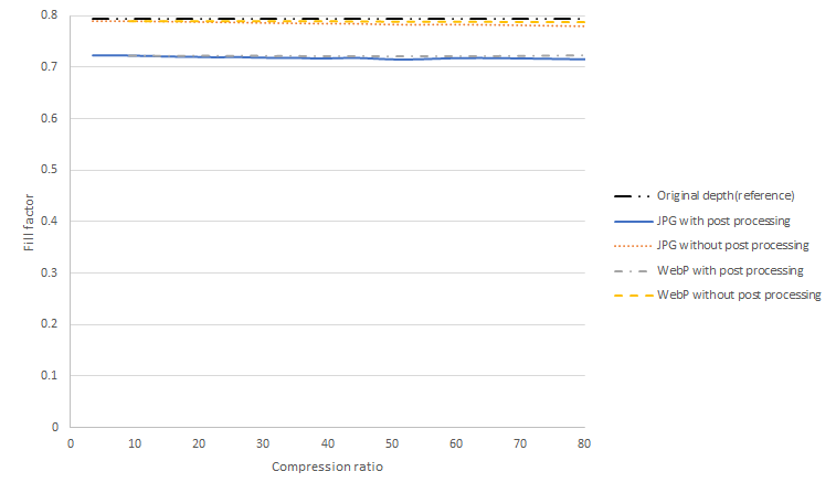
Fig. 9 Compression ratio vs Fill factor of colorized depth image using JPG and WebP
In order to give a better visual impression of what these numbers mean for the point cloud, we show a sequence of images in Figures 10 and 11 that show the point cloud depth quality degradation for increasing compression ratios for both JPG and WebP codecs.
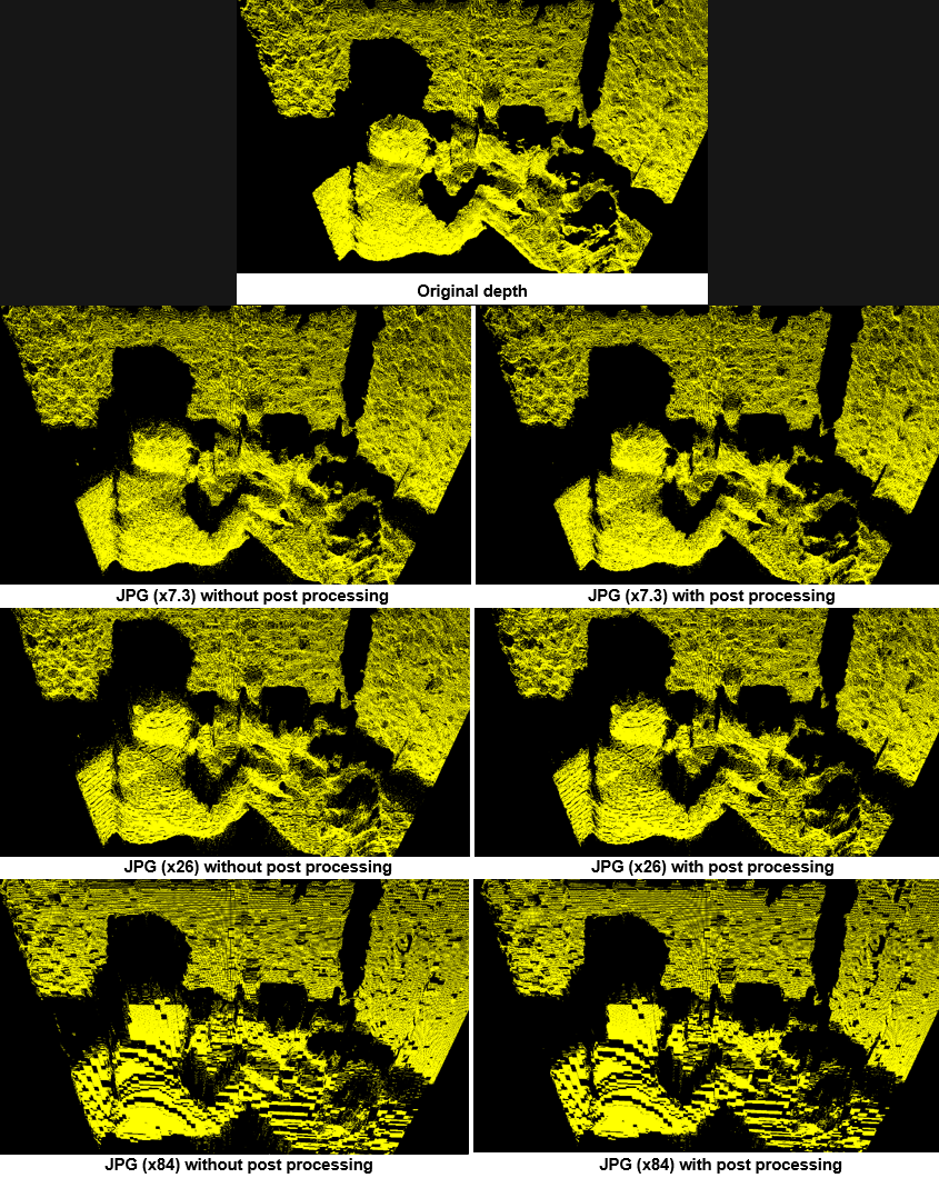
Fig. 10 Point-Cloud scene showing the recovered point-cloud as a function of JPG compression ratio (vertical), and post processing (horizontal).
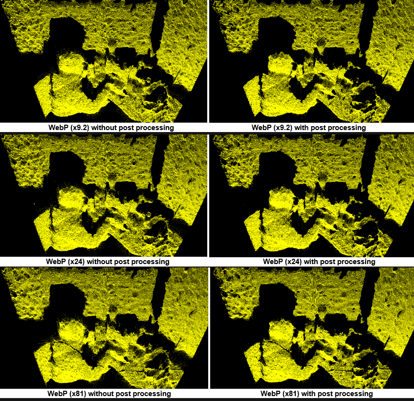
Fig. 11 Point-Cloud scene showing the recovered depth as a function of WebP compression ratio (vertical), and post processing (horizontal).
For JPG compression, Figure 10 shows that as the compression ratio is increased, we start to observe discrete steps in all angled surfaces. The core algorithm of JPG consists of performing discrete cosine transforms (DCT) to each image block in unit of 8×8 pixels. Under highly compressed conditions, we see that blocks are no longer smoothly connected which leads to the appearance of pronounced depth steps. This is in particularly visible for the highest compression image of 84x, where almost no angled surfaces remain, and we observe block-shapes and overlapping flat planes.
By comparison, WebP performs much better for higher compression ratios than JPG and appears to be much better suited to compression of 3D point clouds in general. We see that even at the highest compression ratio, 81x used here, we do not observe any step-like artefacts.
However, for WebP for very high compressions ratios (like 81x), it turns out that the color peaks can no longer be maintained around the yellow, cyan, and purple colors in the middle of each primary color, as seen in the left part of Figure 12 below. This results in the appearance of a different type of depth gap “bandgap” artefact near the boundaries of the respective colors as shown Figure 12 on the right.

Fig. 12 For high compression ratios of WebP, we observe a depth bandgap near the yellow, cyan, and purple colors. Left: Colorized depth image with gray lines representing the yellow, cyan, and purple color areas. Right: A point cloud (from top view) after WebP compression of the colorized image. Gaps in the depth map (indicated by arrows) appear in the the areas corresponding to the gray lines.
Since these depth bandgaps grow with increasing compression ratio, it is necessary to determine an appropriate compression ratio depending on the required accuracy. Alternatively, a method of applying a filter that averages only the boundary portion of each color can be considered, although this is out of scope for this paper. Regarding the flying pixels that occur at all compression ratios, most of them can be removed by applying the above-mentioned post-processing filter.
As described above, the behavior of the depth image at the time of compression varies greatly depending on the codec that is applied. If higher image quality and higher compression ratio are required, video codecs such as H. 264 and HEVC can also be applied using the same approach as that outlined above for still image codecs. Efficient video codecs allow the transfer of depth images over the Internet at a greatly reduced bandwidth.
5. Conclusion
We have in this white paper introduced a straightforward method whereby applying a HUE coloring scheme to a depth map is shown to allow depth maps to be compressed using standard HW-accelerated image compression/decompression codecs, like JPG and WebP. The math behind the colorization and restoration (after compression/decompression) was presented with direct code examples. It was shown that using direct colorization of depth was well suited for short range spans, such as from 0.5m to 2.0m, but that for ranges spanning from 0m to 65m, colorization of disparity maps was recommended instead. We showed that compression did tend to introduce “Flying pixel” artefacts near edges of objects, but that they could be reduced significantly with some simple modified median post-processing filters. The proposed HUE colorization scheme has been integrated into the Intel RealSense SDK. We showed that depth could be inadvertently inverted if min and max depth ranges were chosen to be too close to actual depth. Finally, by comparing image quality based on PSNR and fill factor metrics, we showed that WebP appears to be the better choice, in particular for large compression ratios. Compression ratios of 81x were demonstrated that still showed acceptable image quality.
6. References
[1] Intel RealSense Depth Camera D400 Series: https://www.intelrealsense.com/stereo-depth/
[2] Yannick Morvan, Dirk Farin, and Peter H. N. de With "Novel coding technique for depth images using quadtree decomposition and plane approximation", Proc. SPIE 5960, Visual Communications and Image Processing 2005, 59603I (24 June 2005)
[3] librealsense: https://github.com/IntelRealSense/librealsense
[4] OpenCV: https://opencv.org/
[5] rs-colorization: https://github.com/TetsuriSonoda/rs-colorize
Updated about 1 year ago
