Intel® RealSense™ Tracking Camera T265 and Intel® RealSense™ Depth Camera D435 - Tracking and Depth
Revision 1.0
Author: Phillip Schmidt
Contributors: James Scaife Jr., Michael Harville, Slavik Liman, Adam Ahmed
This article is also available in PDF format.
1. Introduction
1.1 Purpose and Scope of This Document##
In order for a machine to understand the world in 3D, it requires spatial understanding not only about the environment but also about its own position and orientation in space. This is possible with the Intel® RealSense™ Tracking Camera T265 in conjunction with the Intel® RealSense™ Depth Camera D435, rigidly coupled together and spatially aligned. The Intel® RealSense™ Tracking Camera T265 estimates its position and orientation relative to a gravity-aligned static reference frame, while the Intel® RealSense™ Depth Camera D435 performs stereo matching to obtain a dense cloud of 3D scene points. Together this input can be used to obtain a point cloud that is registered with respect to a gravity-aligned static reference frame. This can be a very valuable data stream for applications such as scene mapping and object scanning.
This document describes a sample application that serves as a guide for using and aligning the data streams from the two cameras.
It is not in the scope of the document to discuss the extrinsic calibration and time synchronization between the cameras.
1.2 Organization##
This document is organized into three main parts:
- Overview – Brief overview of the cameras and their combined use.
- Setup – Required Hardware and software setup for running the tracking and depth sample application.
- Running the sample application – Describes how to start the tracking and depth sample application, how to operate and interact with the cameras, and what the expected output is.
2. Overview
2.1 Intel RealSense Depth Camera D435 Overview##
The cameras of the D400 series run (dense) stereo matching on an ASIC to compute the disparity and depth per pixel, which in turn allows estimation of 3D scene points. Please refer to the D400 Series product family datasheet and stereo depth product page for more details.
In the case of a moving depth camera, many applications require the point clouds from different times to be spatially registered, in order to enable efficient accumulation of information. Such registration can be computationally expensive, necessitating additional compute resources or sometimes preventing an application from running in real-time. The T265 tracking camera can be a low-power, low-cost solution to this registration problem.
2.2 Intel RealSense Tracking Camera T265##
Simultaneous Localization and Mapping Systems estimate the position and orientation of a device in space while jointly building an internal map representation of the environment. The Intel® RealSense™ Tracking Camera T265 uses two wide-field-of-view fisheye cameras together with an Inertial Measurement Unit to accomplish this task and outputs its pose relative to a constant initial frame, i.e. translation in meters (m) and orientation as a quaternion with respect to the gravity-aligned initial frame. Please refer to the tracking camera datasheet and tracking product page for further details.
2.3 Spatial Alignment between T265 and D435##
For the correct transformation of points from the depth frame into a world reference frame, the relative transformation between the depth sensor and the body frame, i.e. the pose frame, has to be known as well as the relative pose/motion of the body with respect to (w.r.t.) a static reference frame. For the definition of the respective frames please refer to Figure 1. The relative transformation of the depth frame w.r.t. the pose frame is denoted as H_pose_depth and the relative transformation of the pose frame w.r.t. the world is denoted as H_world_pose. For more details on the definition of the world and pose frame please refer to the tracking camera datasheet. In the following the transformation H_pose_depth is discussed in more detail as it has to be provided by the user in the form of a configuration file as outlined below.
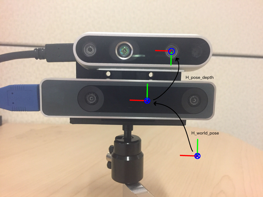
Figure 1. Hardware Setup and Coordinate Frames
The parameters to be provided include:
-
Translation: 3D-translation vector that determines the offset between the depth frame and the pose frame, relative to the pose frame. It is specified as a 3x1 vector in meters. Mathematically written as tx, ty, tz.
-
Rotation: 3D-rotation between the depth frame and the pose frame, relative to the pose frame, specified as a 3x3 rotation matrix.
Mathematically written as [[𝑟11, 𝑟12, 𝑟13], [[𝑟21, 𝑟22, 𝑟23], [𝑟31, 𝑟32, 𝑟33]].
The combined homogenous transformation transforms a point from the depth frame into the pose frame. Mathematically this transformation is written as follows:

The scope of this document includes only the spatial alignment between the T265 and D435 camera streams. The timestamps for the two devices are available through librealsense on the same host-correlated system time and should be used for temporal alignment of the data, e.g. using interpolation if necessary. This temporal alignment is not in the scope of this document.
3. Setup
This section describes the required hardware and software setup for running the tracking and depth sample application.
3.1 Hardware##
The hardware required includes:
- Intel® RealSense™ Depth Camera D435
- USB-C cable
- Intel® RealSense™ Tracking Camera T265
- USB Micro B cable
- A 3D-printed mount (see Section 3.1.4)
- 2x M3x18mm screws, 2x M3x10mm screws, 1/4-20 insert nut
- Host system running Windows 10 or Ubuntu 16.04.
3.1.1 Devices###
Intel® RealSense™ Tracking Camera T265 and Intel® RealSense™ Depth Camera D435 as shown below are used for the tracking and depth sample respectively.
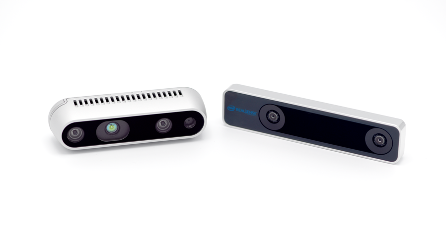
Figure 3-1. D435 and T265 Devices
3.1.2 USB###
A USB 3.0 Type-C cable to connect the D435 and a USB Micro B cable to connect the T265 to the host computer.
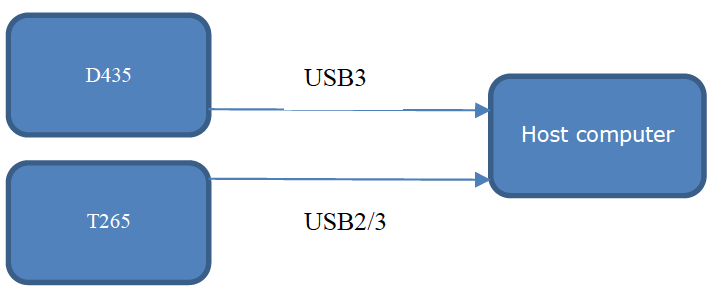
Figure 3-2. System Diagram
3.1.3 Host Computer###
A computer running Windows 10 or Ubuntu 16.04. For a full list of supported operating system please refer to the librealsense README.md.
3.1.4 Mount###
A 3D-print of the sample design depicted in Figure 3-3 can be used to rigidly attach both cameras. The transformation between the two cameras for this mount is provided and can be used to transform points from the depth camera to the tracking camera frame.
Two M3x10mm screws can be used to mount the T265 below and two M3x18mm screws for the D435 above (in the depicted orientation in Figure 1 and Figure 3-3). In this orientation a 1/4-20 insert nut can be used to mount the assembly on a tripod (or any other standard camera mount).
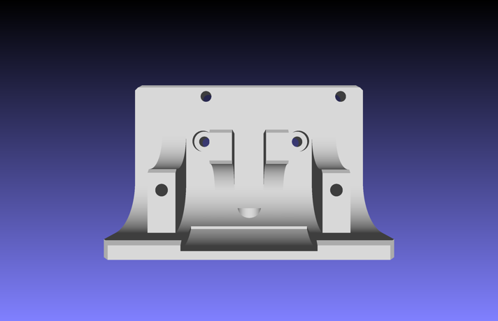
Figure 3-3. T265 and D435 Bracket
3.2 Software##
Install the latest release of the Intel® RealSense™ SDK 2.0 on the host computer. Table 3-1 contains pointers to the SDK homepage, GitHub* repository where you can download the latest release, and the SDK documentation, a direct pointer to the tracking and depth sample and its respective documentation, as well as a pointer to the tracking and depth sample configuration file.
3.2.1 Configuration File###
The tracking and depth sample configuration file is a text file that stores the homogeneous transformation between D435 and T265 in the following format:
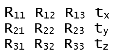
where Rij are the components of the row-major rotation matrix R and [tx, ty, tz]T is the translation vector (in meters). The transformation expresses the D435 depth frame (which coincides with the left infrared imager) with respect to the T265 body frame (as defined in the Tracking Camera Datasheet). Please also refer to Figure 1 for a visualization of the coordinate frames.
The configuration file is expected to be located in the same folder as the tracking and depth sample executable and is copied to the respective folder during the build process. The file can be edited (or replaced) for custom configurations that are different from the mount that is provided with the sample. Please ensure that rotation matrix R is a valid rotation matrix and orthonormal.
Table 3-1. Intel RealSense SDK 2.0 Resources
| Resource | URL |
|---|---|
| Intel® RealSense™ SDK 2.0 Home Page | https://www.intelrealsense.com/developers/ |
| GitHub* repository | https://github.com/IntelRealSense/librealsense |
| SDK 2.0 Documentation | https://dev.intelrealsense.com/docs |
| Tracking and Depth Sample | https://github.com/IntelRealSense/librealsense/tree/master/examples/tracking-and-depth |
| Tracking and Depth Sample Configuration File | https://github.com/IntelRealSense/librealsense/blob/master/examples/tracking-and-depth/H_t265_d400.cfg |
4. Running the Tracking and Depth Sample Application
4.1 Data Flow Overview##
The general data flow in the tracking and depth sample is depicted below. The point cloud from the D435 and the T265 pose are streamed to the host via USB. The pose estimate is used, together with the extrinsic transformation between the two cameras, to transform the point cloud and finally to display it.

Figure 4-1. Tracking and Depth Sample Data Flow Diagram
4.2 Connect Device to Computer##
Connect the devices using the USB-cable to the PC where Intel® RealSense™ SDK 2.0 has been installed.
4.3 Running the rs-tracking-and-depth executable##
4.3.1 Starting the process###
Use a bash terminal on Ubuntu or a command prompt in Windows to navigate to the folder where the rs-depth-and-tracking executable was built.
From a command prompt run:
./rs-depth-and-tracking
Note: It is recommended that the user verifies the configuration file (Sec. 3.2.1) was copied to the same folder prior to running the executable.
4.3.2 Moving the viewpoint###
If the extrinsic configuration file is found in the same folder and the executable starts successfully with both cameras connected, a window will open that displays the point cloud in a gravity-aligned reference frame together with the estimated trajectory of the T265. The points are colored using the RGB data from the D435. The initial view configuration is similar to that of the rs-pointcloud sample, to allow easy comparison of the point cloud output with and without tracking.
The view can be changed by using the left mouse button to click into the window and drag left/right or up/down to rotate yaw and pitch respectively. The mouse wheel can be used to zoom in and out of the scene.
4.3.3 Moving the cameras###
When moving the cameras while facing a static scene, the camera pair should appear much like a “flashlight” illuminating different parts of a constant world. In contrast, without the pose registration provided by the T265 camera, the output of a single moving depth camera would appear to be a continuously changing point cloud without any scene context. Please note that some lag can be noticeable, due to the relative latency between the latest samples of the two camera streams, and this lag is typically proportional to the velocity of the camera pair. For applications in which it is important to reduce this lag, the poses should be interpolated based on the synchronized timestamps.
To test the extrinsic calibration accuracy, the cameras can be rotated around all three axes while observing a point in the scene. With good calibration, the offset of the point should remain within a few pixels (for close objects at approx. 0.3 to 0.5 meter) throughout the motions.
4.3.4 Shutdown###
The application can be shut down by either closing the window or pressing CTRL-C in the terminal to kill the process.
5. Code Overview
The example is based on the pointcloud example. Please also refer to its respective documentation.
First, include the librealsense header:
#include <librealsense2/rs.hpp> // Include RealSense Cross Platform API
Next, we prepare a very short helper library encapsulating the basic OpenGL rendering and window management:
#include "example.hpp" // Include short list of convenience functions for rendering
We also include the STL header for std::min and std::max, and for std::ifstream to parse the homogeneous transformation matrix from a text file. Next, we define a state struct and two helper functions. state and register_glfw_callbacks handle the point cloud’s rotation in the application, and draw_pointcloud_wrt_world makes all the OpenGL calls necessary to display the pointcloud.
// Struct for managing rotation of pointcloud view
struct state { double yaw, pitch, last_x, last_y; bool ml; float offset_x, offset_y; texture tex; };

// Helper functions
void register_glfw_callbacks(window& app, state& app_state);
draw_pointcloud_wrt_world(float width, float height, glfw_state& app_state, rs2::points& points, rs2_pose& pose, float H_t265_d400[16]);
The example.hpp header allow us to easily open a new window and prepare textures for rendering. The state class (declared above) is used for interacting with the mouse, with the help of some callbacks registered through glfw.
// Create a simple OpenGL window for rendering:
window app(1280, 720, "RealSense Tracking and Depth Example");
// Construct an object to manage view state
state app_state = { 0, 0, 0, 0, false, 0, 0, 0 };
// register callbacks to allow manipulation of the pointcloud
register_glfw_callbacks(app, app_state);
We are going to use classes within the rs2 namespace:
using namespace rs2;
As part of the API, we offer a pointcloud class which calculates a pointcloud and the corresponding texture mapping from depth to color frames. To make sure we always have something to display, we also make a rs2::points object to store the results of the pointcloud calculation.
// Declare pointcloud object, for calculating pointcloud and texture mappings
pointcloud pc = rs2::context().create_pointcloud();
// We want the points object to be persistent so we can display the last cloud when a frame drops
rs2::points points;
We declare a rs2_pose object to store the latest pose as reported by T265.
rs2_pose pose;
To stream from multiple device, please also refer to the multicam example. First, a common context is created and a (separate) pipeline is started for each of the queried devices.
// Start a streaming pipe per each connected device
for (auto&& dev : ctx.query_devices())
{
    rs2::pipeline pipe(ctx);
    rs2::config cfg;
    cfg.enable_device(dev.get_info(RS2_CAMERA_INFO_SERIAL_NUMBER));
    pipe.start(cfg);
    pipelines.emplace_back(pipe);
}
The extrinsics between the streams, namely depth and pose, are loaded from a configuration file that has to be provided in the form of a row-major homogeneous 4-by-4 matrix.
While the app is running, we loop over the pipelines and wait for the respective color, depth and pose frames:
for (auto &&pipe : pipelines) // loop over pipelines
        […]
	auto frames = pipe.wait_for_frames();  // Wait for the next set of frames from the camera
Using helper functions of the frameset object, we check for new depth and color frames. Then we pass it to the pointcloud object to use as texture, and also give it to OpenGL with the help of the texture class. OpenGL will use the new data for pointcloud rendering.
auto depth = frames.get_depth_frame();

// Generate the pointcloud and texture mappings
points = pc.calculate(depth);

auto color = frames.get_color_frame();

// Tell pointcloud object to map to this color frame
pc.map_to(color);

// Upload the color frame to OpenGL
app_state.tex.upload(color);
In a similar way, we get the pose data from the pose frame of the frameset:
auto pose_frame = frames.get_pose_frame();
if (pose_frame) {
    pose = pose_frame.get_pose_data();
}
Finally, we call draw_pointcloud_wrt_world to draw the pointcloud with respect to a common (fixed) world frame. This is done by moving the observing camera according to the transformation reported by T265 and extrinsics to the depth stream (instead of transforming the scene by the inverse which results in the same relative motion).
draw_pointcloud_wrt_world(app.width(), app.height(), app_state, points, pose, H_t265_d400);
draw_pointcloud_wrt_world primarily calls OpenGL, but the critical portion iterates over all the points in the pointcloud, and where we have depth data, we upload the point's coordinates and texture mapping coordinates to OpenGL.
/* this segment actually prints the pointcloud */
auto vertices = points.get_vertices();              // get vertices
auto tex_coords = points.get_texture_coordinates(); // and texture coordinates
for (int i = 0; i < points.size(); i++)
{
    if (vertices[i].z)
    {
        // upload the point and texture coordinates only for points we have depth data for
        glVertex3fv(vertices[i]);
        glTexCoord2fv(tex_coords[i]);
    }
}
The second critical portion changes the viewport according to the provided transformation.
// viewing matrix
glMatrixMode(GL_MODELVIEW);
glPushMatrix();

GLfloat H_world_t265[16];
quat2mat(pose.rotation, H_world_t265);
H_world_t265[12] = pose.translation.x;
H_world_t265[13] = pose.translation.y;
H_world_t265[14] = pose.translation.z;

glMultMatrixf(H_world_t265);
glMultMatrixf(H_t265_d400);
Please note that OpenGL uses column-major matrices.
Updated over 2 years ago
