Intel® RealSense™ Depth Camera over Ethernet
Authors: Philip Krejov, Anders Grunnet-Jepsen
Revision 1.0
This article is also available in PDF format.
This document gives a brief introduction to the hardware and software requirements for communicating with a Intel® RealSense™ depth camera over Ethernet.
The GigE Vision standard defines the process by which a host machine can discover, control, and acquire images from one or more GigE Vision cameras. However, Intel RealSense cameras are USB2 & USB3 devices and do not support GigE Vision directly out of the box and can therefore not be connected directly to an ethernet hub or network. Instead, in this document, we describe an application level Client-Server approach that can be used to discover, control, and acquire images from Intel RealSense cameras over ethernet. We provide this solution as a “Getting Started” open-source guide. We note that, for simplicity, it does not adhere to the GigE Vision standard. It does however still include the capabilities to discover and acquire images from one or more remote Intel RealSense cameras.
Gigabit Ethernet##
Gigabit Ethernet is a data transmission standard based on the IEEE 802.3 protocol. This standard is the successor to the Ethernet and “Fast Ethernet” standards that are widely used today. While Ethernet and Fast Ethernet are limited to 10 Mb/s and 100 Mb/s, respectively, the Gigabit Ethernet standard reaches a transmission speed of up to 1000 Mb/s. It also allows for a wide array of cabling technologies including CAT 5, fiber optic, and wireless. However, while the theoretical transmission speed is 125 MB/s, in reality most hard drives, for example, max out at 60MB/sec, or 480Mbps. For comparison we show a table below of the bandwidth for some standard Intel RealSense™ camera configurations. It is immediately clear that to enable multiple depth cameras to be on the same network simultaneously, a solution must include some sort of data compression or reduction. So why are we not focusing here instead on using 10GigE, the ethernet standard with 10x the bandwidth? The answer is that while the solution presented here can certainly be extended to that, 10GigE tends to be much costlier and challenging to deal with, and is therefore not a common go-to solution in robotics or embedded solutions.
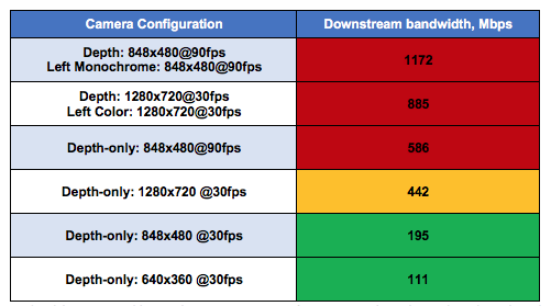
Table 1: Bandwidth consumed by Intel RealSense Camera configurations. The color coding describes the limit of streaming a single camera’s uncompressed streams on a Gigabit ethernet network (red=not possible).
Streaming depth over Gigabit Ethernet brings with it long list of desirable features:
- Cabling: CAT 5 cables are comparatively inexpensive and can be cut to exactly the right length. They enable long transmission distances, with up to 100m without the need for a hub. This is far greater than any other major bus used in the machine vision industry.
- Bandwidth: With transmission rates of up to 125 Mb/s, Gigabit Ethernet is faster than USB1.0, USB 2.0, IEEE 1394a, and IEEE 1394b. While it is not the highest bandwidth solution, it is perhaps the most widely adopted long range wiring solution.
- Multiple Clients: the code sample can be modified to allow multiple clients to connect to the camera servers, allowing multiple applications/machines to receive the cameras feeds.
- Network Capable: It becomes possible to network cameras and access them remotely from any computer. Moreover, it makes it possible to more easily acquire images from multiple cameras, albeit with the limitation that they all share the same bandwidth pipe of course.
- Future Growth: With 10 Gb and 100 Gb Ethernet standards on their way, the GigE Vision standard can easily scale to use the higher transmission rates available.
- Internet Broadcast: The server in theory could be connected to the internet, making it possible to stream depth over the internet
Getting Started##
The purpose of this paper is to build out a concrete solution and share all our considerations. We will focus our example on demonstrating networked data collection from multiple viewpoints. Multiview point cloud capture have been shown to be extremely valuable for both the collection and annotation of real world data, as well as for complete instantaneous volumetric capture. For this reason, two main modes of operation will be discussed – live streaming and temporary recording.
First, we present a live streaming system based on UP boards (https://up-board.org/)). UP boards are miniature credit-card sized compute boards with Intel processors that are easily connected to an Intel RealSense camera. The UP boards are used to capture and broadcasts depth frames as soon as they are available. This is useful for applications that wish to provide live data for processing, for example for real-time robotics or surveillance applications.
The second mode of operation is to use the UP Board as a temporary recording device. The buffering branch of the “EtherSense” repository offers a slightly modified version of the server that captures 900 frames on receiving a connection to the client. This mode of operation allows for depth cameras to record at full resolution and framerate for a limited time (for example 900 frames) before transmitting the captured frames to the client for storage or processing at a lower bandwidth. This mode of operation is useful for data collection at native resolution and allows recordings in a distributed fashion without bandwidth concerns limiting the data collection rate or quality.
Software Architecture##
The source code for “EtherSense” can be found at the following address:
https://github.com/krejov100/EtherSense
The accompanying code base is written using Python allowing native cross platform support and simplicity of use. For this example, we installed Ubuntu on the UP boards.
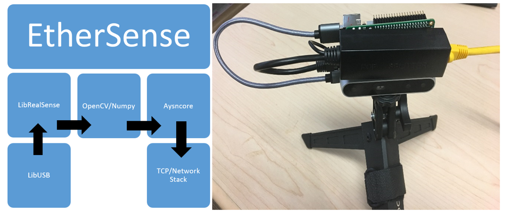
Figure 2: Software and Hardware overview for an EtherSense server that transmits video streams from a RealSense camera over ethernet.
Device Discovery##
A “Server” is defined as a single UP board (Server host) with a connected Intel RealSense Camera, serving up depth camera streams. A “Client host” (ex: a user) will have a “Client application” running on it with the ability to connect to multiple device servers, as shown in Figure 3.
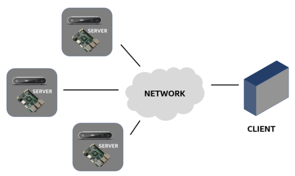
Figure 3: Client-Server Model for networking Intel RealSense Cameras
The server script is relatively straight forward, with LibRealSense being a dependency. “EtherSense” is as a thin application running on the Server-host. It calls LibRealSense on the server-host and LibRealSense is subsequently responsible for communicating with the Camera over USB.
When a Server-host (i.e. an UP device) is powered on, it attempts to acquire an IP address in the following order:
- Persistent IP: If the Device Server has been assigned a persistent IP, it will assume that IP address.
- DHCP Server: If no IP address has already been assigned, the device server searches the network for a DHCP server and requests the DHCP server to assign an IP address.
Turning now to the Client (i.e. user), the Client application attempts to discover all available Servers (i.e cameras). Currently this is only done during initialization, however it is possible to modify our example such that it periodically requests the addresses of new cameras on the network.
The Client application sends a specific multicast message to the network. This is a message all servers are programmed to listen for. On receipt of the multicast message the servers respond with a request to open a connection to the client using TCP with the following command:
self.create_socket(socket.AF_INET, socket.SOCK_STREAM)
Once a connection is established, EtherSenseServer starts to stream frames to the Client using:
handle_write(self)
However, on first call the function determines that there are no frames available for transmission and so performs a request to:
update_frame(self)
which is responsible for pulling a frame from the Intel RealSense camera, which is then resized and broken into smaller packets that are sent via Asyncore.
Below we show the total set of window streams that appear during connection to 5 Clients. As can be seen, each of the camera stream windows has a port number and a title which is used to identify where they come from.
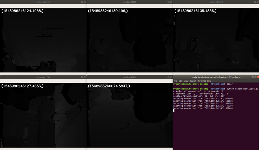
Figure 4. Client Application showing connection to the depth streams from 5 servers.
UDP/TCP Protocols##
Like Ethernet and Fast Ethernet, most of the communication packets on Gigabit Ethernet are transported using either the TCP or the UDP protocol. Transmission Control Protocol (TCP or TCP/IP) is more popular than User Datagram Protocol (UDP) because TCP can guarantee packet delivery and packet order (i.e. Packets are delivered in the same order that they were sent). Such reliability is possible because packet checking and resend mechanisms are built into the TCP protocol. While UDP cannot guarantee packet delivery or order, it can achieve higher transmission rates since there is less overhead involved in packet checking.
The software example provided with LibRealSense is implemented using TCP for frame packet transition which differs from GigE vision which uses UDP for streaming frames. In doing so the demo sample has reduced complexity over that of a UDP implementation. This is because a UDP implementation would require additional components to be responsible for packet ordering and handling of packet drops. While using TCP means there is packet-wise overhead regarding acknowledgment messages, it’s use ensures that frames are not dropped, are in order, and complete. The accompanying code base aims at simplicity over a complete feature set and as such the minimal information is broadcast on a per frame basis.

Figure 5. Simple format of a TCP packets used for video streaming
Our example can of course be extended to allow for additional information to be packaged for broadcast. Below we show a revised packet schema for transmitting laser state, as well as both color and depth.
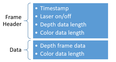
Figure 6. Slightly more complex TCP packet format, incorporating camera settings and multiple streams.
Network bandwidth##
As mentioned earlier, it is possible to saturate the bandwidth of the Ethernet connection, and while we have successfully tested 5 Servers (with single stream depth at 640x480, 30fps) connected to the same client, performance is expected to degrade beyond that.
There are a number of compression strategies that can be considered for increasing the number of cameras or resolution of streams. These can fairly easily be implemented on the UP boards and the client, but won't be covered in detail in our example code:
- Use a smart post-processing decimation filter that is part of libRealSense. A decimation factor of 3 will result in 9x reduction in bandwidth, without a significant reduction in depth performance (see the RealSense post-processing white paper).
- self.decimate_filter.set_option(rs.option.filter_magnitude, 2)
- Use UDP: Transmitting frames using UDP and allowing for frame drop can improve the effective bandwidth a small amount.
- Reduce the depth channel from 16bit to 8bit, which will improve the throughput 2x.
- Reduce the input depth image resolution. The tradeoff is unfortunately in both depth XY and Z performance.
- cfg.enable_stream(rs.stream.depth, 640, 480, rs.format.z16, 30)
- Addition compression of the color and depth streams, either frame wise or better yet, temporal.
- Use local recording of the depth data into a buffer, with asynchronous frame transfer (buffer branch).
Additional information regarding the bandwidth required for one or more cameras can be found in the following white paper.
UP Board Hardware##
There are a number of platforms that can be used as a Server-host with LibRealSense. In this paper we explored the use of the UP Boards which is a Single Board Computer (SBC) that is low cost and capable of running LibRealSense for interfacing with the Intel RealSense depth camera.
The UP Board has both a single USB3 micro port and multiple USB2 ports. The USB2 ports can be used to interface to the Intel RealSense Cameras in the case of using low resolution or frame rate steaming. Moreover, a single UP board could in fact manage the streaming of multiple Intel RealSense Cameras onto the network.
Power Supply##
The UP Board requires a 5V 4A power supply which can be provided using the provided wall adaptor. However, in many cases for ease of deployment, Power-over-Ethernet (PoE) is a nice alternative that obviates the need for the wall adaptor.
Power-over- Ethernet (PoE) describes any of several standard or ad-hoc systems which pass electric power along with data on twisted pair Ethernet cabling. This allows a single cable to provide both data connection and electric power to devices such as wireless access points, IP cameras, and VoIP phones.
The original IEEE 802.3af-2003 PoE standard provides up to 15.4 W of DC power (minimum 44 V DC and 350 mA[2][3]) on each port.[4] Only 12.95 W is assured to be available at the powered device as some power dissipates in the cable. Since an UP board tends to consume less than 5W and an Intel RealSense camera consumes about 1.5W (depending on number of streams, projector power, resolution, and frame rate), PoE is a viable option.
The following is a PoE breakout header for the UP Board provided by AAEON.
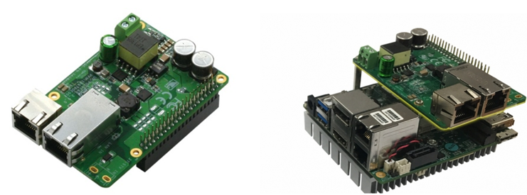
Figure 7. Power-over-Ethernet breakout board for the UP board
This can be found at the following address: https://www.aaeon.com/en/p/iot-gateway-boards-up-poe-hat.
There are general purpose PoE break-out solutions that are available online. The power output port of these devices is 5V 2.0A with over voltage protection. However, we caution that this is below the recommend current needed to power the UP Board and can lead to instability. Also, we note that in most instances we recommend running the UP Board headless - without a display attached – as it helps to maintain kernel stability. When purchasing PoE breakouts, it is important to check both the break-out voltage (5V) and the connector type (5.5mm Barrel connector).
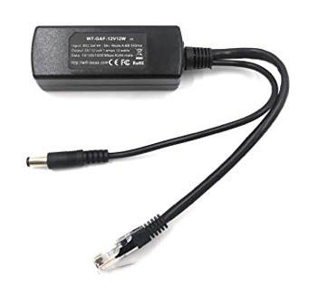
Figure 8. Example Power-over-Ethernet splitter solution
The following image shows the UP board being powered using the PoE splitter, allowing both the data and power for the Intel RealSense camera to delivered using only a single cable.
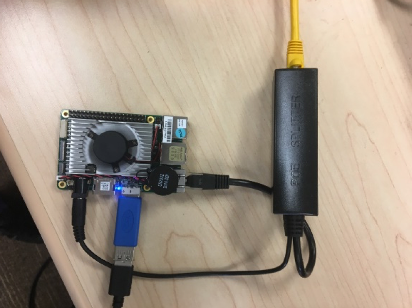
Figure 9. UP board being powered by PoE
It also shows the connection to the USB3 port which requires a Micro USB3 – USB3 adaptor. The use of such adaptors can be avoided operating the cameras at lower resolution supported by USB2.
In Figure 10 we show is the same setup replicated across four cameras, used in our testing.
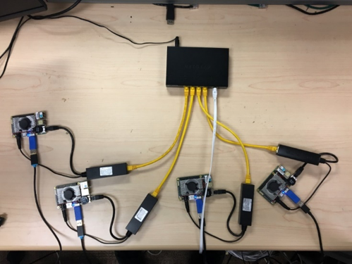
Figure 10. Configuration of 4 UP Boards connected to 4 Intel RealSense cameras, and powered by directly over the ethernet connection.
In figure 11 we show an alternative Ethernet system used to control of multiple “5x Intel RealSense Multiview Stage” (on the right), all connected using Ethernet.

Figure 11. Ethernet server used with 5x UP Boards capturing depth from a Multiview Intel RealSense cameras stage.
Summary##
In this document we explored the use of low-cost single board computers (SBC) to operate as an intermediary for acquiring frames from Intel RealSense cameras and broadcasting the captured frames over Ethernet. The document provides insight in to the transmission protocols used as well as the software design considerations using in the creation of a demo application. All the source code has been made openly availably. The paper also explores powering the SBC using PoE allowing for single cable camera deployment.
Updated over 5 years ago
