High-Dynamic Range with Stereoscopic Depth Cameras
Authors: Sergey Dorodnicov, Anders Grunnet-Jepsen, Evgeni Raikhel, Remi Bettan
Rev 0.3
This article is also available in PDF format
1. Introduction
A common challenge encountered with imaging is to capture scenes that may consist simultaneously of both very dark and very bright areas. While normal imagers may have great low light response and also work in bright sunlight, this versatility is usually achieved by changing the gain and/or exposure for the whole image at once. However, there are many examples where the dynamic range of a sensor may not be large enough. A common example is what happens when a camera flash lights up a nearby face. This will usually either result in an over-exposed face, or under-exposed background. For robots and vehicles many other examples can be even more problematic as they need to be able to drive autonomously while encountering many other challenging examples, such as sidewalks in the shadow of a brightly lit buildings; entering/exiting doorways or tunnels where indoor/outdoor lighting differs; or driving in the dark while facing oncoming traffic with high beams on. These types of scenes can also cause problems for the Intel RealSense Stereo Depth Cameras, because they rely on processing depth from two good quality left and right images. The most common problem occurs when the internal IR pattern projector is being used to illuminate a dark scene. The intensity of the dots will fall off as the square of the distance away, resulting in a very large brightness difference between near and far objects.
High-Dynamic Range (HDR) imaging describes family of techniques designed to overcome the limitations of standard sensors by merging two or more frames into a single higher dynamic range synthetic stream . This is widely used in mixed-lighting photography and image processing. In the context of stereoscopic depth cameras, higher dynamic range can mean higher depth fill-rate due to access to more and better features. This brings immediate value for collision avoidance, reducing the chance of missing an obstacle due to challenging lighting conditions.
This paper will introduce all the necessary concepts required to understand Depth-HDR, and presents a simple and efficient method for HDR depth sensing using Intel RealSense D400 series depth cameras. Note that HDR imaging for the visible light RGB sensor is outside the scope of this white-paper.
2. Sensor Control
2.1 Exposure & Gain
The exposure time of a sensor represents the time the sensor is a sensitive to light. It is not necessarily the same as the frame time, as it is possible, for example, to expose a sensor for 1 ms, but only read it out every 33 ms (30 fps). . Intel RealSense D400 devices have separate exposure control for the visible light RGB sensor and infrared left-right pair inside the stereo module. For the stereo pair, exposure is measured in µs (microseconds, 10-6 of a second) and depending on the specific sensor, can range from 1 µs to around 160 ms. Lower values correspond to less light captured by the sensor, and vice versa. As a result, indoor scenes can often benefit from higher exposure times (usually 5-30 ms) while outdoor scenes require require much lower exposure (usually <1 ms), as seen in Figure 1 below.
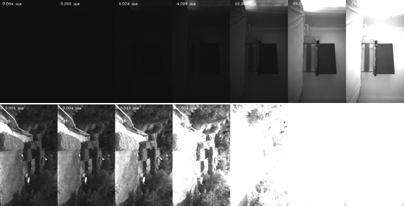
Figure 1. Effect of different exposure values on indoor scene (top) vs outdoor scene (bottom). Outdoor scenes need much lower exposure (usually <1 ms), while indoor dark scenes may need >5 ms.
In addition to exposure, the gain of the sensor can also be controlled. Unlike exposure, gain does not influence the amount of light being collected but rather amplifies the existing signal (using analog amplification in for low values, and digital amplification for high values).

Figure 2. Effect of modifying camera gain. The larger the gain, the brighter the image, as shown above for gain ranging from 25 to 225.
The drawback of digital amplification is the amount of noise it introduces, because it scales but the signal and the noise of the image as shown in Figure 3.

Figure 3. Similar level of brightness achieved by adjusting the exposure (left) vs adjusting gain (right)
The benefit of using gain with shorter exposure is that it reduces motion related effects such as motion blur, as shown in Figure 4.

Figure 4. Same scene captured with high gain and short exposure (left) vs low gain and longer exposure (right). This scene was captured with the global shutter imagers of the D435, so there are no additional rolling shutter artifacts of the fan.
2.2 Global vs Rolling Shutter
Other related concepts in digital imaging are global and rolling shutter sensors. Rolling shutter is a method of image capture in which each frame is captured by moving scanlines vertically across the scene rapidly. In other words, not all parts of the image of the scene are recorded at exactly the same instant. This is in contrast with global shutter in which the entire frame is captured at the same instant. Because of this, rolling shutter sensors can introduce visual artifacts when capturing rapidly moving objects, as shown in Figure 5.
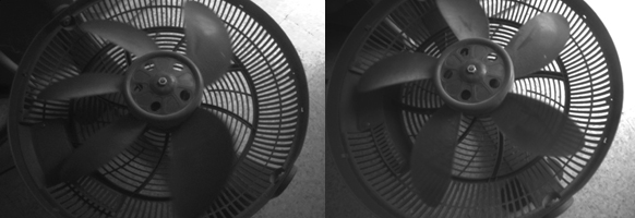
Figure 5. Same scene of a moving fan captured using rolling shutter sensor (left) and global shutter sensor (right). The Left image was taken with the D415 which has a rolling shutter, while the right image was taken with the D435 which uses global shutters.
2.3 Under and Over Exposure
When a signal is being converted to a digital frame it is quantized based on the effective dynamic range of the sensor and number of bits available. Any value below the minimal or above maximal threshold will be clipped. This can results in areas of over- and/or under-exposure. Areas of overexposure would show up as almost all white regions, while area of underexposure would appear almost black. These are undesirable in regular photography, but are especially problematic for stereo depth sensing since stereo matching relies on availability of sharp and clearly visible features in proximity of every pixel. Figure 6 shows two different problematic scenes – the top has an underexposed region (a TV screen), while the bottom has an over-exposed white wall on the right side. Both these cases result in zero (black) or bad depth values in the problem areas. The preview stream of the IR image helps us identify both under-exposed regions having brightness near 0, and over-exposed regions having brightness near 255.
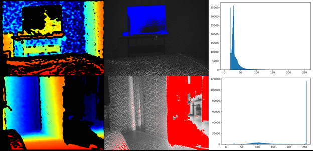
Figure 6. Effects of under and over exposure: left – depth image, middle – infrared image with highlighted overexposed pixels in red and underexposed pixels in blue, right – infrared image histogram
Note that some pixels appear to be over/under-exposed in the infrared image but still contain seemingly valid depth. This is due to fact that the D4 ASIC internally has access to the 10-bit data from the sensor, while only an 8-bits stream is available to display on the host PC. This gives stereo matching algorithm a x4 effective dynamic range compared to what we see in the preview of the left image stream.
2.4 Manual vs Auto-Exposure
By default the sensor is configured to start in auto-exposure mode. In this mode, the camera firmware will automatically adjust exposure and gain values trying to reach a certain preset image intensity
Setting rs.option.enable_auto_exposure option to 0 or setting specific values to rs.option.exposure or rs.option.gain will disable auto exposure.
cfg = rs.config()
cfg.enable_stream(rs.stream.infrared, 1) # For D400 infrared streams are split between 1 and 2, for left and right

p = rs.pipeline()
profile = p.start(cfg)

sensor = profile.get_device().query_sensors()[0] # First sensor is the stereo module

# Query minimum and maximum supported values
max_exp = sensor.get_option_range(rs.option.exposure).max
min_exp = sensor.get_option_range(rs.option.exposure).min

sensor.set_option(rs.option.exposure, min_exp)
# After applying new exposure value its recommended to wait for several frames to make sure the change takes effect
# Alternatively, the user can know when exposure was changed using per-frame metadata
for j in range(1, 10):
    frames = p.wait_for_frames()
    ir = frames.get_infrared_frame(1)
    if ir.supports_frame_metadata(rs.frame_metadata_value.actual_exposure):
        if ir.get_frame_metadata(rs.frame_metadata_value.actual_exposure) == min_exp:
            break # Exposure change took place, no need to keep waiting
Code 1. Manually controlling sensor exposure value
When in auto-exposure mode the user can indirectly control the resulting exposure and gain setting by adjusting theauto-exposure set-point, available under advanced controls. This can be used if default left infrared image (or left RGB) is either too dark or too bright for specific use case.

Figure 7. Effect of adjusting auto-exposure set-point for an indoor (top)and outdoor (bottom) scene. The setpoint is increased going from left side images to right-side images. Note that in the outdoor scene the image cannot get any darker on the left, due to sensor minimal exposure limitations.
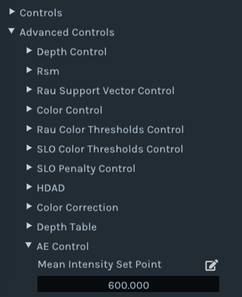
Figure 8. Modifying auto-exposure intensity setpoint in Intel RealSense Viewer
Modifying intensity setpoint is possible using rs400_advanced_mode API:
cfg = rs.config()
cfg.enable_stream(rs.stream.infrared, 1) # For D400 infrared streams are split between 1 and 2, for left and right

p = rs.pipeline()
profile = p.start(cfg)
advnc_mode = rs.rs400_advanced_mode(profile.get_device())

# Read-modify-write of the AE control table
ae_ctrl = advnc_mode.get_ae_control()
ae_ctrl.meanIntensitySetPoint = 1000
advnc_mode.set_ae_control(ae_ctrl)

# After modifying the setpoint its recommended to wait for several frames to make sure the change takes effect
for j in range(1, 10):
    p.wait_for_frames()
Code 2. Influencing exposure and gain by modifying intensity setpoint in auto-exposure mode
2.5 Exposure and Framerate
One final aspect to note is that there is a limitation to the maximum exposure time that can be set depending on the camera framerate, as shown in Table 1
| Framerate (Hz) | Max Exposure Time (microseconds) |
|---|---|
| 90 | 11111 |
| 60 | 16666 |
| 30 | 33333 |
| 15 | 66666 |
| 6 | 166000 |
Table 1. Max exposure per framerate
In manual exposure mode, setting exposure time to a value above what is allowed for the selected framerate will force a reduction in framerate. This can be monitored using frame metadata rs.frame_metadata_value.actual_fps. However, when auto-exposure is enabled it the frame rate determines the max exposure time. . This means that an indoor scene running at 90 fps may look darker with auto-exposure compared to 30 fps, as the frame rate limits the exposure to 11.1 ms for 90 fps, but allows exposure to increase to 33.3 ms for 30 fps.
3. High Dynamic Range
High dynamic range (HDR) imaging is technically the ability for an imaging system to see in both very dark and very bright scenes (by using gain, exposure, binning, more bits etc.). Wide dynamic range (WDR) is the ability to have a large dynamic range in the same scene, and is the preferred term for surveillance cameras. However, HDR is today the accepted terminology for both these cases. To solve the problem of limited dynamic range many designs rely on capturing multiple images with different exposures and combining them into a single HDR image. Given the limitations of D400 hardware, it is not possible to fuse multiple exposed color and depth images on the embedded ASIC. .Instead we present here a method that runs on the host CPU and that fuses two depth images directly using data from two consecutive frames . This feature requires firmware 5.12.8.100+ and SDK 2.39. We emphasize that we do not here discuss combining the color (or IR) images from these exposures to output a better color (or RGB) image, as many techniques exists for doing that. Instead we only focus on increasing the depth dynamic range beyond the 10bit dynamic imaging range that exist today. Also, this should not be confused depth ranging resolution, which today is 16 bits.
3.1 HDR with Intel RealSense Viewer
In order to configure the camera to work in HDR mode, a new HDR Enabled control was introduced on compatible devices. In the Intel RealSense Viewer, the user needs to enable Depth and Infrared streams for this to work. Since every two frames will generate a single HDR output, we will configure the device to twice the normal fps. In addition, to see exactly what the camera is doing lets disable post-processing for now. The HDR function will fuse consecutive frames to generate an HDR depth. It does this by merging High Exposure + Low Exposure, and then Low Exposure + High Exposure, and so on. The resultant frame rate is still 60 fps, but there will effectively be a latency of 2 frames.
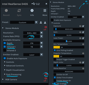
Figure 9. Configuring the hardware for HDR in Intel RealSense Viewer
The camera will start streaming, flickering between the two pre-specified exposures. Opening the metadata panel and pausing the stream will reveal more information. Note – per-frame metadata is necessary for HDR merging. Please refer to official documentation if some or all of the metadata is not visible. We will describe later how to set the separate exposure and gain values.
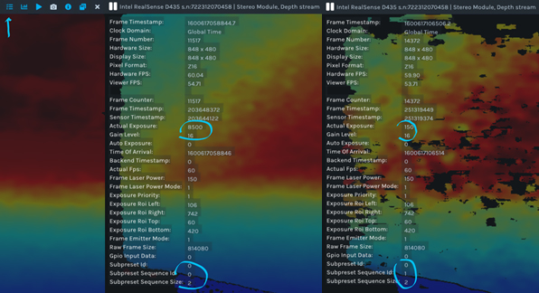
Figure 10. Examining frame metadata of an HDR stream
The relevant metadata items are:
• Actual Exposure – exposure that was used for current frame
• Actual Gain – gain that was used for current frame
• Subpreset Sequence Size – length of the HDR sequence
• Subpreset Sequence ID – step number inside the HDR sequence of the current frame (zero based)
• Subpreset ID – user-assigned identifier of current HDR sequence
In order to generate fused depth HDR stream, HDR Merge post-processing needs to be enabled:

Figure 11. Enabling Depth HDR Merge under post-processing
Depth HDR fusion follows the same principles as the rest of the post-processing inside Intel RealSense SDK –
• Post-processing is explicit – extra computation work is not done without request from the user
• Post-processing is optional – access to raw data is preserved
• Post-processing is open – source code is available under src/proc
Note:
After enabling HDR Merge, the depth stream will be replaced with synthetic HDR depth. The side effect will be that the left image (aka infrared) stream will flicker. Since merging left image frames is a standard image processing task, it is not re-implemented as part of Intel RealSense SDK. Instead we recommend using industry standard tools like OpenCV for that task (example below).
Note: After enabling HDR Merge, the depth stream will be replaced with synthetic HDR depth. The side effect will be that the left image (aka infrared) stream will flicker. Since merging left image frames is a standard image processing task, it is not re-implemented as part of Intel RealSense SDK. Instead we recommend using industry standard tools like OpenCV for that task (example below).
In addition to HDR depth fusion, the SDK provides a simple way of splitting the flickering stream into its individual sequence components. This is done using Sequence ID Filter algorithm:
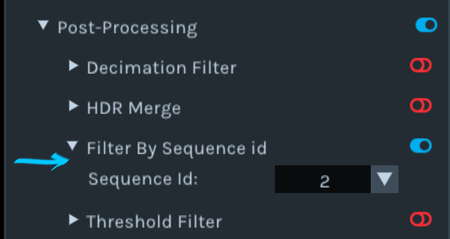
Figure 12. Filtering the stream by sequence ID, 1-based
Note: HDR mode cannot be directly combined with Emitter On-Off mode, but both can be filtered by sequence ID.
HDR depth mode can be further fine-tuned using the following controls:
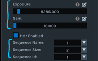
Figure 13. Advanced HDR control
To select exposure and gain values for each specific step, you will need to change the sequence ID to the step number (1-based) and modify regular exposure & gain controls. To add more steps, modify sequence size control (assuming hardware support is available). Finally, giving a new value to a sequence name will be reflected in the Subpreset ID metadata field.
3.2 Controlling HDR programmatically
Similar to how it was done in Intel RealSense Viewer, HDR can be enabled using rs.option.hdr_enabled option:
cfg = rs.config()
cfg.enable_stream(rs.stream.infrared,1, 848, 480, rs.format.y8, 60)
cfg.enable_stream(rs.stream.depth, 848, 480, rs.format.z16, 60)

p = rs.pipeline()
profile = p.start(cfg)

sensor = profile.get_device().query_sensors()[0]
sensor.set_option(rs.option.hdr_enabled, 1)
Code 3. Configuring streaming in HDR mode
At this point it is possible to access the flickering stream directly or to use built-in HDR Merge post-processing algorithm:
hdr = rs.hdr_merge() # needs to be declared once

while True:
    frames = p.wait_for_frames()
    frames = hdr.process(frames).as_frameset()
    depth_frame = frames.get_depth_frame()
Code 4. Using HDR merge post-processing algorithm to fuse multiple frames
The resulting depth stream can be further enhanced using SDK algorithms, such as point-cloud, alignment and other types of depth post-processing.
3.3 Example
In the following scene, we highlight the challenge of picking a single exposure by looking at capturing a scene that has both direct sunlight and shadow in the same frame, as shown in Figure 14. The histogram on the right shows a bimodal distribution of brightness values, and we certainly see a spike at 255 indicating lots of saturated pixels:

Figure 14. Mixed indoor and outdoor scene. Left: Depth map , Middle: Left monochrome image with inpainting to show saturation (red) and underexposed (blue) regions. . Right: left image brightness histogram, showing the the bi-modal distribution of high and low exposure.
The built-in auto-exposure algorithm has dealt with the scene fairly well, but due to the majority of the frame being in shadow, the autoexpsure converged to exposure resulting in oversaturated image for the outdoor part of the scene:

Figure 15. Mixed indoor and outdoor scene using auto-exposure. Note that we have in-painted red color in the left image to indicate regions where we have identified saturation. The corresponding regions on the depth map on the right are showing some streaking artifacts.
The Depth HDR algorithm is able to produce depth with significalty less artifacts and a higher overall fill-rate:

Figure 16. HDR stream – high exposure (top left), low exposure (top right), merged depth (bottom)
3.4 Generating HDR Infrared Images
Infrared images can also be merged, using standard algorithms available in OpenCV:
images = (cv2.cvtColor(ir1,cv2.COLOR_GRAY2RGB), cv2.cvtColor(ir2,cv2.COLOR_GRAY2RGB))
merge_mertens = cv2.createMergeMertens()
fusion = merge_mertens.process(images) * 255
Code 5. Performing tone-mapping on infrared images using OpenCV
When mapping the HDR image back to a lower dynamic range so that it can be displayed on a screen, the resulting image brings out many more features from both high and low exposure sub-frames, s, as shown in Figure 17. This process of making a higher dynamic range image to a smaller dynamic range is called tone-mapping
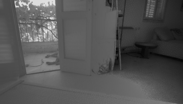
Figure 17. Tone-mapped left monochrome image generated from two input levels of exposure
4. Performance Analysis
4.1 When HDR Depth should be considered?
While D400 auto-exposure is very capable in indoor, outdoor and some mixed environments, we found HDR to be a useful tool in extreme mixed-lighting environments, like indoor near windows or bright LCD panels. Using two distinct exposures can also help reduce artifacts due to reflections and glare, as shown in Figure 18.
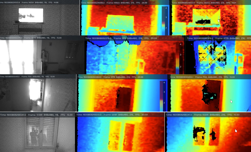
Figure 18. Different types of use cases for HDR depth. Left: the monochrome image. Middle: HDR depth map. Right: Regular Auto-exposure Depth map). The HDR depth is able to mitigate many saturation artifacts and tend so show a better depth with higher fill factor.
4.2 Effect of HDR on Depth KPIs
Generally speaking, when configured properly the HDR depth we strive to ensure that the overall depth performance, as measured by the key performance indicators (KPI), are improved. This includes the plane-fit standard deviation of flat walls, fill-rate (valid depth points), and absolute depth error. . In figure 19 we show results from an indoor lab scene.
We see that both the plane fit RMS and Z-std are not significantly affected by introduction of HDR

Figure 19. Plane fit RMSE and Z-std metrics for indoor lab scene. The blue bar is with HDR exposure of (1 ms & 10 ms). The red bar is with auto exposure of (0.16 ms & 16 ms), while the grey bar is the simple single frame auto-exposure. The y-axis is the error in mm. Smaller is better. We see no significant change across these KPIs. The x-axis is the distance away from the object in mm.
However, we when we turn to the fill-rate and absolute accuracy, we do see an improvement, as shown in Figure 20. Using HDR Depth (the red and blue bars) is seen increases the fill-rate giving more valid depth pixels. We also observe a measurable positive impact on Z-accuracy, presumably due to better outlier filtering.

Figure 20. Same as 19, for average fill-rate (left) and average absolute Z-accuracy (right). For fill rate, we see an improvement (higher values) for the two HDR results (blue, red).
4.3 Limitations
While this technique can be useful in some cases, it has its limitations. First, depth HDR is implemented on the host and has higher latency and CPU utilization (500-700 µs on i7-CPU) compared to built-in auto-exposure algorithm. We also at this time do not provide an option to combine HDR with auto-exposure as one of the steps. This means finding effecting exposure and gain values for HDR in specific environment can be a challenge. Finally, since we are combining frames with different timestamps, this technique is sensitive to motion. Both rapid motion in the scene and motion of the camera can generate artifacts similar to the effect of the temporal filter.
5. References
- Intel RealSense D400 Camera Series datasheet - https://dev.intelrealsense.com/docs/intel-realsense-d400-series-product-family-datasheet
- Rolling vs Global Shutter - https://en.wikipedia.org/wiki/Rolling_shutter
- HDR imaging with OpenCV - https://docs.opencv.org/3.4/d2/df0/tutorial_py_hdr.html
Updated over 2 years ago
