High-speed capture mode of Intel® RealSense™ Depth Camera D435
Rev 1.2
Authors: Tetsuri Sonoda, John N. Sweetser, Tri Khuong, Shirit Brook, Anders Grunnet-Jepsen
This article is also available in PDF format
In this white-paper, we explore the effects of scene- and camera-motion on the performance of Intel RealSense depth cameras D400 series, and we specifically focus on introducing a new 300 fps high-speed capture mode for the D435 model. We show how this mode can be used to capture fast motion, but also how it can be used to enhance depth performance. To fully appreciate the need for high-speed capture, we also take the time in this paper to explore various motion artifacts and performance limitations of the current modes of operation of both the D415 and D435 models, and the considerations that need to be taken into account when capturing very high-speed motion. The D415 and D435 cameras are shown to behave differently, and artefacts are seen to depend on both distance to objects, lighting conditions, projector illumination, and whether the fast motion comes from the camera moving or objects moving in the scene.
1. Introduction
The Intel RealSense Depth camera D435 is capable of capturing depth with a wide Field-of-View (FOV) of ~90x58 degrees at 90fps with a resolution of 848 x 480, producing up to 36.6 Million depth points per second. In this paper we explore the benefits of introducing a new mode in which we configure the global shutters in the D435 stereo depth imager to capture at 300fps, albeit with a narrower vertical FOV of 840x100. This means we are performing about the same number of depth calculations per second and therefore not increasing the bandwidth of data being transmitted. This new mode is illustrated in Figure 1.

Fig. 1: Depth map from an Intel RealSense D435 depth camera operating at 848x480 (left image) versus the new high-speed capture mode (right image) with a resolution of 848x100, cropped to the vertical center.
This trade-off with vertical FOV allows us to explore three primary benefits of high-frame-rate capture. First, a higher frame rate obviously allows us to capture faster motion. This will enable usages such as the ability to capture optically both the speed and complete 3D trajectory of a ball flying at high speeds, like a baseball fast pitch. Second, we will show that under bright lighting conditions or high projector power, we can use this high frame-rate mode to reduce the depth measurement noise by capturing at high frame rates and applying multi-frame averaging to enhance the depth measurement while still achieving normal effective frame rates of, say, 30fps. The basic reasoning is that if the depth noise is stochastic from frame-to-frame, then we should in principle see a noise reduction of sqrt (300/30), or 3.16x. Finally, since the Intel on-chip Self-Calibration feature (covered in another white paper) scales in speed directly with the frame rate, introducing a 256x144 300fps mode, means that it can be sped up 3.3x compared to 90fps mode.
In the following we start by explaining how to enable and use high-speed capture mode.
2. How to enable high-speed capture mode
The high-speed depth capture will be released in firmware version 5.12.4.0. It will be available for the download from the Firmware Releases section [1]. To install firmware, Device Firmware Update (DFU) tool is available, or it can be installed directly with the Intel RealSense Viewer. After the firmware installation, launch the Intel RealSense Viewer application bundled in Intel RealSense SDK to check if it can be set into high-speed depth capture mode 848x100 at 300fps (for D435 cameras). Also note that for best high-speed operation, it is recommended to not have any other devices connected to the USB port, and to limit the use of simultaneous applications that place a high load on the host CPU.
2.1 High-speed mode configuration with Intel RealSense SDK 2.0
Here, we describe a simple high-speed depth capture example by modifying librealsense2 C++ example. In the original “rs-capture” example in librealsense2, it opens a default stream:
// Declare RealSense pipeline, encapsulating the actual device and sensors
rs2::pipeline pipe;
    pipe.start();
By adding configuration with pipe.start, it enables a specific stream configuration, image format, resolution and framerate capture such as high-speed capture mode as below.
// Config for streams
rs2::config* config = new rs2::config();

// Request a specific configuration
config->enable_stream(RS2_STREAM_DEPTH, 0, 848, 100, RS2_FORMAT_Z16, 300);

// Declare RealSense pipeline, encapsulating the actual device and sensors
rs2::pipeline pipe;

pipe.start(*config);
2.2 Enabling infrared stream for monochrome image capture
We recommended to NOT enable the RGB camera stream simultaneously, as it will only operate at 30fps, capture will not be synchronized, and depth capture can become unstable on some PC platforms. Instead, 300fps monochrome image streams can be enabled (RS2_STREAM_INFRARED) as shown below. In these 2 streams, index 1 is the left infrared stream which is aligned perfectly to the depth stream as shown in Figure 2.
config->enable_stream(RS2_STREAM_DEPTH, 0, 848, 100, RS2_FORMAT_Z16, 300);
config->enable_stream(RS2_STREAM_INFRARED, 1, 848, 100, RS2_FORMAT_Y8, 300);
config->enable_stream(RS2_STREAM_INFRARED, 2, 848, 100, RS2_FORMAT_Y8, 300);
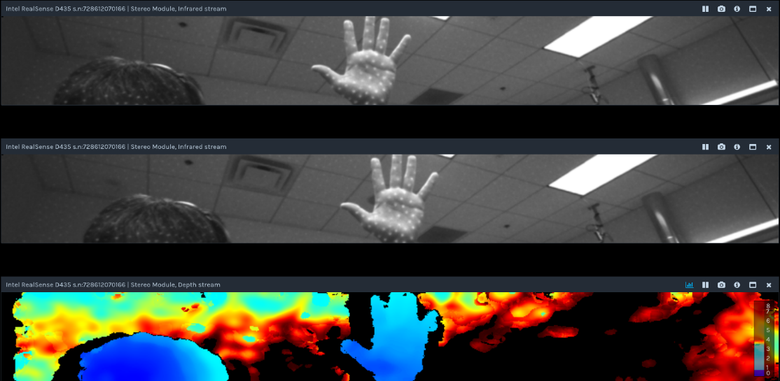
Fig. 2 Infrared and depth stream images. Top: Right infrared stream (index 2). Middle: Left infrared stream (index 1). Bottom: Depth stream (index 0), which is seen to be aligned to left infrared stream.
3. Measurement of fast moving objects using high-speed mode.
Having described the mechanisms of capture, we now turn to specific examples and considerations for capturing high speed motion. We start by noting that the definition of "fast" is actually not an absolute number, because the motion observed by the camera changes with the distance to the moving object. Clearly, the closer the moving object is to the camera, the more transverse movement there will be between captured frames.
3.1 Target movement per frame
The higher the frame rate, the smaller the change in position or size will become between consecutive frames for moving objects. As the distance between the moving object and the depth camera increases, the movement of objects in consecutive image decreases. Therefore, if high speed capture is desired, one could argue that the distance between the camera and the object should simply be increased, if physically permitted. Whilst this is true, there are two limitations: 1. The accuracy of range of D400 Series depth cameras scales quadratically with the inverse of the distance to the object, and 2. The object image size shrinks and the transverse resolution degrades linearly with range to object. The relationship between depth camera and a moving object is shown in the Figure 3 below.

Fig. 3: Illustration of the parameters that affect capture quality, showing a ball (on right side) moving in front a pinhole camera model of an Intel RealSense camera (on left side).
When the object at distance d[m] from the camera moves at the speed vxy[m/s], the movement t [pixel] of the object in the image between frames is expressed by the following equation:
Equation 1
where, p [fps] is frame rate, f [pixel] is focal length of depth camera, given by
Equation 2
with xres [pixel] being depth image x resolution, Hfov [rad] being the depth image’s horizontal FOV.
Typically, f is about 645 pixels for the D435 1280x720 resolution mode, and about 940 pixels for the D415 1280x720 resolution mode. Target object size in captured image ri [pixel] is expressed by the following equation.
Equation 3
It is very instructive to now relate this to a few real-world examples. Table 1 below shows examples of the relationship between the transverse velocity of a moving object and the amount of frame-to-frame movement, for some selected camera-to-object distances.
| Target object | Speed [m/s] | Object Distance [m] | Camera | Resolution mode | Object Size [m(pixel)] | Frame-to-Frame Translation in image [pixel] |
|---|---|---|---|---|---|---|
| Pedestrian | 1.2 | 2 | D415 | 1280x720, 30fps | 1.7(799) | 19 |
| Sprint runner | 10 | 2 | D435 | 848x480, 60fps | 1.7(363) | 36 |
| Car on freeway (65mph) | 30 | 8 | D435 | 848x480, 60fps | 5.0(267) | 27 |
| Billiard ball break shot (27mph) | 12 | 1 | D435 | 848x480, 90fps | 0.053(23) | 55 |
| Moving target of experiment | 15 | 0.5 | D435 | 848x100, 300fps | 0.035(22) | 43 |
| Table-tennis ball serve (69mph) | 31 | 1 | D435 | 848x100, 300fps | 0.044(19) | 44 |
| Baseball pitch (105mph) | 47 | 1 | D435 | 848x100, 300fps | 0.073(31) | 67 |
| Tennis ball serve (164mph) | 73 | 1 | D435 | 848x100, 300fps | 0.067(29) | 104 |
| Golf ball drive shot (211mph) | 94 | 1 | D435 | 848x100, 300fps | 0.042(18) | 134 |
*Table 1: Examples of moving objects speed, size, optimal depth camera resolution mode and per frame translation in captured image. Item 4, “The moving object experiment”, will be considered in more detail. To properly track the speed and velocity of an object it should be visible in multiple frames, which necessitates that the last column should be much smaller than the frame resolution (column 5).
32 Experiment to measure fast moving object
In order to dive deeper and quantify some specific examples of the effects of high-speed transverse motion, we created the simple “electric fan” experiment shown in Figure 4.
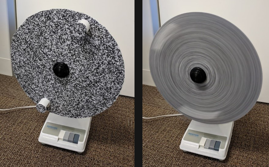
Fig. 4: A modified electric fan. Two cylindrical objects are attached to a rotating disc to act as fast-moving targets.
We attached two 35mm diameter cylindrical targets to the rotating disc as target objects. Both rotating disc and fast-moving targets are textured in this controlled experiment. A measurement app was created to track the cylinders by using simple depth-image background subtraction, and center position and velocity were measured between frames using a Connected Components approach based on size thresholding. A typical result can be seen in figure 5 below.

Fig. 5: Speed measurement of moving cylinders from Figure 4. LEFT: 400fps capture, and RIGHT: 30fps capture.
Each image shows original depth (upper), moving object depth and motion vector (middle), and measured speed (bottom). At 400fps, the object speed of ~15 m/sec is measured correctly, whereas for the 30fps mode it fails.
In this experiment, we measured up to about 15 m/sec object speeds, limited by the fan rotation speed, and compared 400fps vs 30 fps captures. This example shows how the 30fps mode is not able to sample enough images in time to properly capture the velocity. As seen in Table 1 (last column), the interframe motion is only 32 pixels when operating at 400 fps, but would be 426 pixels at 30fps, which is too large for accurate depth vector estimation.
3.3 Rolling Shutter D415 versus Global Shutter D435
When discussing motion capture by imaging systems, a complete analysis should clearly also address all aspects of capture, including image blur and system shutter artefacts. It is well known that Global Shutter imagers are generally preferred for high speed motion capture because they do not suffer from rolling shutter artefacts [3]. This is also one clear difference between the Intel RealSense Depth Camera D415 which uses rolling shutters, and the D435 model which uses global shutters. Another important difference is that the D435 model has about 5x the light sensitivity. This is extremely important for fast image capture. Concretely this means that while the D415 in a low-light office environment might need 33ms to capture a good quality image, the D435 would only need less than 6ms.
In this section we will concentrate on quantifying the motion artefact differences between the D435 and D415 models, so we can better illustrate the conditions under which a D415 model can sufficiently capture motion, and the conditions under which it would become necessary to switch to a D435. It turns out that the motion sensitivity can be very different depending on many factors, such as whether the object or camera is moving, or whether the pattern projector is on or off.
In the first experiment, we use a rotating blade with fixed position cameras, and adjust the blade rotation rate from maximum speed down to rest. The blade is placed in front of a surface (wall or curtain). The Intel RealSense depth camera is mounted on a tripod and pointed at the blade. The camera distance is set such that the blade fills most of the FOV (~1m for D415, 0.68m for D435). The blade is spun and a sequence of frames (depth, RGB, or point cloud) is captured. Tests are run with both D415 and D435 cameras running at 30 fps and 1280x720 resolution. A variety of conditions are captured with different configurations of blade and background texture, with and without emitter.

Fig. 6. Sequential frames of depth (left) and monochrome images (right) of a rotating blade with a stationary camera and emitter enabled for D415 and D435. Motion blur and depth artifact (evident as false depth values near blade edges)
are clearly visible for D415 and absent for D435. Cameras are running at 30fps, 1280x720.
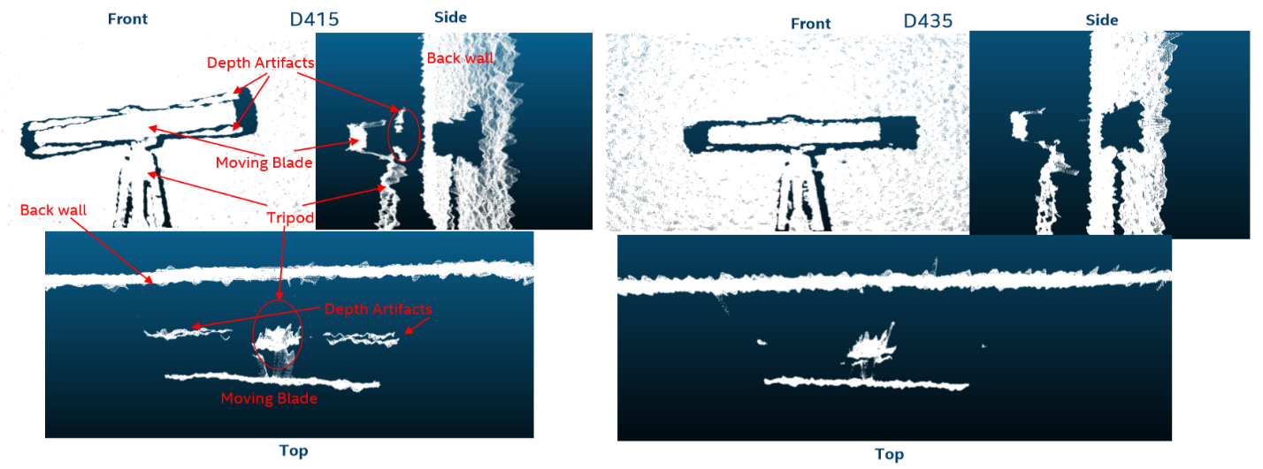
Fig. 7: Point Cloud images (Front, Side, and top views) of rotating blade with stationary D415 and D435 cameras. Motion blur and depth artefact (evident as false depth values near blade edges) are clearly visible in D415 and negligible in D435.
As can be seen in Figures 6 and 7, when the fan is rotated, the D415 starts to exhibit artefacts at high rotation speeds. Interestingly, these artefacts appear as false depth points roughly midway between the blade and the background. Note that for this configuration, the projector pattern will NOT become blurred, irrespective of the speed of the rotating fan. In other words, there is no motion blur of the projection pattern.
The benefit of using a rotating fan for this experiment is that it allows us to quantify in a single snapshot the effect of speed. Near the center there is very little motion and near the tips there is maximum motion. The effective speed near the blade tip is ~4 m/s for D415 at 1m and ~4.7 m/s for D435 at 0.68m which is equivalent to ~7m/s at 1m distance. The depth motion artefact in the D415 images are seen to increase with radial distance (and hence speed). From this we can estimate that the speed required to observe onset of artefact is 1.7 - 2 m/s @ 1m (~7km/hr) for the D415, which is about the speed of a hand waving fast.
3.4 Camera Movement
Another experiment was performed to see the effects of rotational motion of the camera itself, and not object motion. A stationary object (box) on a tabletop is viewed during camera motion. The camera is rotated manually about horizontal and vertical axes. Captured images are shown below for horizontal motion. The projector pattern was turned on.
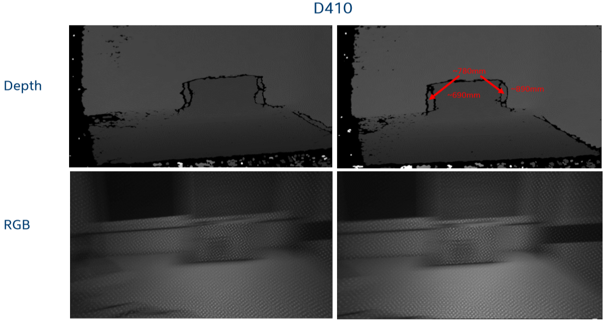
Fig. 8: Sequential frames (L to R) of front face of a box while D415 camera is rotated horizontally. Top: D415 depth image. Bottom: Corresponding D415 monochrome image. The pattern projection on the D415 was on. Note that the background is blurred but the projection pattern is not. For vertical motion the same effects are observed on the leading and following edges of the motion.
In Figure 8, a D415 is rotated so the box moves about 130 pixels between frames at 30 fps which corresponds to an effective speed ~4m/s at a distance of ~1m. Depth artefacts again appear, this time along front and back sides of the box, again as false edges at an intermediate depth between box face and back wall. However, we again note that the active projector pattern is NOT being blurred by motion, but the background is clearly seen to be blurred. The projector is effectively helping to reduce artifacts stemming from image blur.
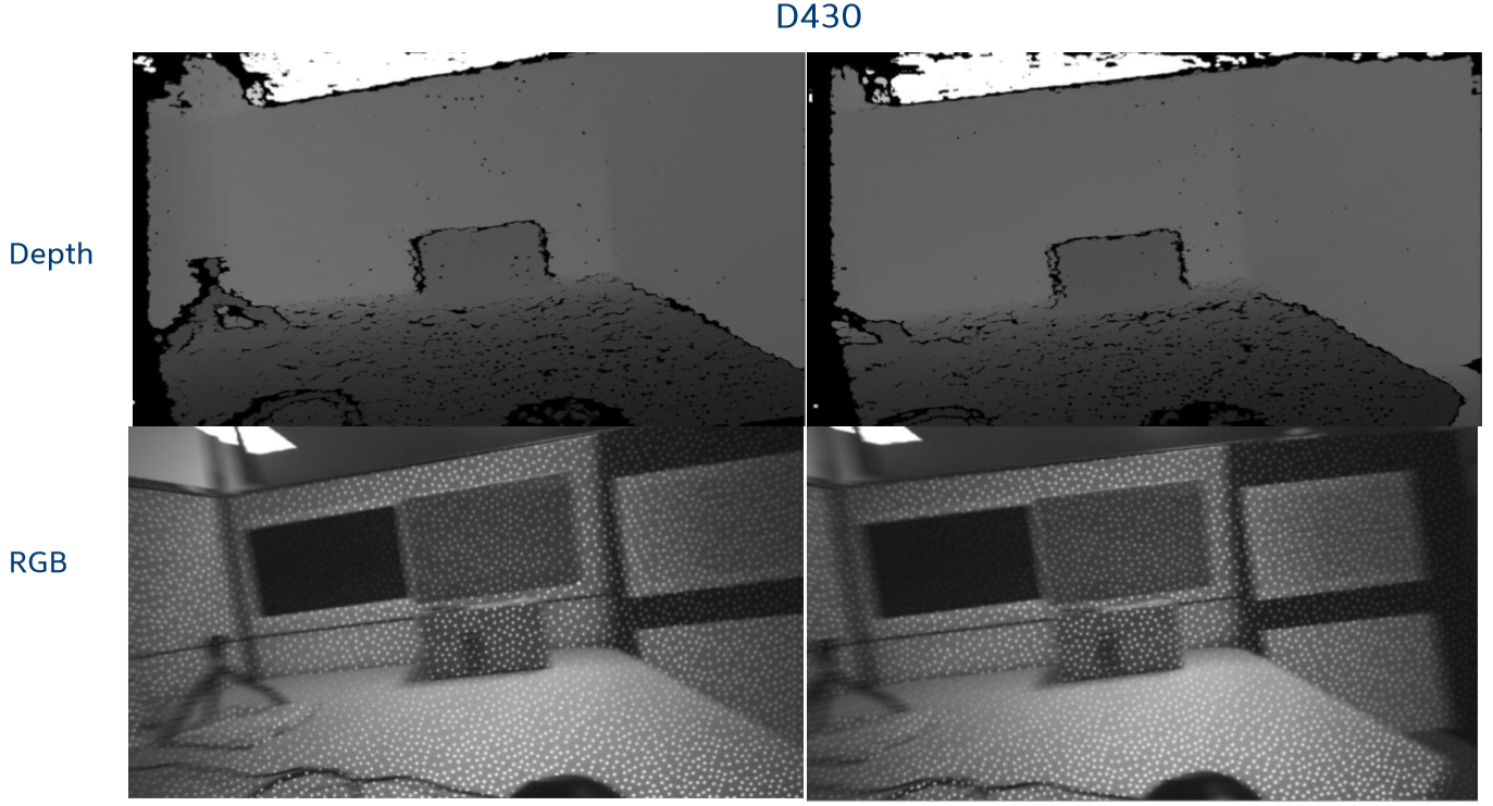
Fig. 9: Horizontal motion. Sequential frames (left to right) of front face of a box while D435 camera is rotated horizontally.
Top: D430 depth image. Bottom: corresponding D435 grayscale image. Almost no motion artifacts are observed.
Figure 9 shows the corresponding results for the D435, with a box motion of about 85 pixels between frames at 30 fps or an effective speed about 4m/s at a distance of 1m. Any depth artefacts are minimal and virtually no motion blur is visible in the monochrome image.
3.5 Analysis of motion blur with and without emitter
In the previous experiments the projector was kept on. It turns out that for low light environments and long exposures and low frame rates, any motion of the scene will introduce significant blurring of the images, which in turn will have immediate deleterious effects on depth. However, because the projector pattern stays essentially fixed in space relative to the camera, its pattern is not blurred and depth is preserved, even during motion.
In the following we look at the effects of turning OFF the projector. Blur is something that is common to both rolling shutter and global shutter cameras. However, the main advantage of the global shutter D435 is that because it is ~5x more sensitive, it will be able to have a 5x lower exposure time and image blurring for the same lighting conditions, compared to the D415.
For a textured scene with no pattern projector, we can quantify the blur length op [pixel] by the following equation.
Equation 4
where, vxy [m/s] is the moving object speed in x and y direction as described in Figure 3, vz [m/s] is the moving object speed in z direction, x [m] is the offset from depth camera center axis described in Figure 3, and s[s] is the exposure time.
An actual blurred image from a D435 stereo camera is shown in Figure 10, for motions in xy- and z-directions, with emitter turned off.

Fig.10 Top: Images of a slow-moving ball. Bottom: Blurred images of a faster moving ball without dot projector. Left: Transverse movement in xy-plane. Right: Movement in z-direction. Captured images are taken with an extremely long exposure time (150ms) to make blur easier to see.
If the projector dot pattern is on, the blur length oa [pixel] of the dots is expressed simply by:
Equation 5
Here, b [m] is the baseline of depth camera, which for D435 is 50mm, and D415 is 55mm. Thus, the pattern projector is very effective at reducing the effects of image blur. Figure 11 demonstrates the identical images to those seen in Figure 10, but with projector turned on. Two observations are worth noting: 1. Due to the long exposure time, the projection patterns from the foreground ball and background wall overlap near leading and trailing edges of the moving object, marked by the circles on the left of Figure 11. 2. For z-direction movement, the projected dots elongate and blur slightly along the x-axis, as highlighted by the circle on the right of Figure 11.

Fig.11: Same as Figure 10, but with dot projector turned on. Left: Transverse motion in xy plane. Right: Movement of ball in z-direction. Captured images are taken with a same long exposure time of 150ms. In comparison with Figure 10, it is clear that the dots experience much smaller blur than the object itself.
3.6 Minimum object size (MOS)
We mentioned earlier that high-speed objects can be captured better when farther away from the camera, simply because the objects are seen for multiple frames. However, there are two trade-offs to consider when capturing at a farther distance: 1. The depth noise increases as the square of the distance from the object, and 2. There is a limit to how small the object can be and still reliably be tracked. In this section we focus on minimum detectable object size, or MOS. While we have seen that a projector can help mitigate motion artifacts for low light conditions, unfortunately the dot density of the D435 active emitter is fairly small (only about 5000 dots) which is much less than the stereo depth resolution. Therefore, with the active emitter, the smallest measurable object size will be larger compared to that of a well textured object (and no emitter).
In order to experimentally determine the minimum measurable object size (aka MOS) under both conditions, an experiment was performed in which multiple objects of different sizes (1cm, 1.5cm, 2cm) with and without texture were measured. The objects were suspended in mid-air with a thin string at a distance of 1 m from D435.
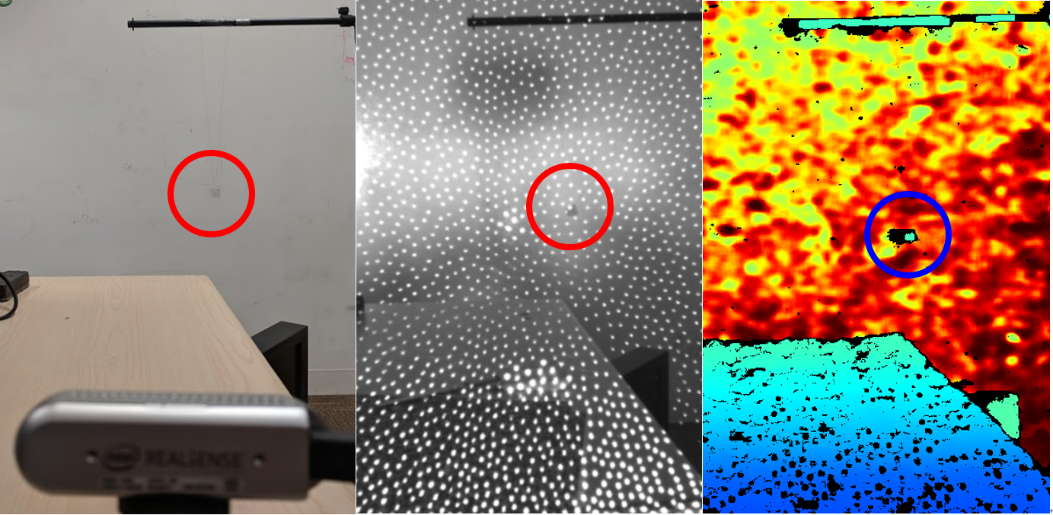
Fig. 12: Showing small 20mm object suspended in air, as indicated by circle. Left: Image of D435 Camera pointing at small object. Center: Infrared image of object. Right: Depth map.
The result is shown in Figure 12 and summarized in table 2, below. With emitter only (no texture), objects need to be 13 pixels or larger, whereas ~9 pixels was sufficient for textured objects.
| Target size (Pixel size) | 10mm (6.45 pixel) | 15mm (9.68 pixel) | 20mm (12.9 pixel) |
|---|---|---|---|
| Textured target without emitter | Not captured | Stable captured | Stable captured |
| White target with emitter | Not captured | Unstable captured | Stable captured |
Table 2. Captured result of each size textured and white targets
To conclude this section, we have explored some of the many factors that need to be considered in order to properly capture fast moving objects. Specifically, we found that it is best to 1. Run at high frame rate, 2. Have a lot of light (to reduce the exposure time), 3. Not be too close to the object, as it increases inter-frame distance moved by the object, 4. Be close enough to the object so that it is not below the minimum-detectable size, and 5. Turn on the pattern projector to help mitigate motion artifacts.
4. Accuracy improvement by averaging multiple depth frames
As mentioned earlier, another important benefit of high frame-rate capture is the ability to improve depth capture performance, by simply capturing at higher frame rates, and using temporal averaging to reduce the noise. The basic premise is that if only a small exposure time is needed to capture a scene, such as 3.3ms or less, then it makes sense to capture at the fastest rate (e.g., 300Hz), and simply average frames, even if the final application does not need the high frame rate.
4.1 Minimum required exposure time
The minimum exposure time required for the D435 for different brightness environments was measured by adjusting the illumination of a well-textured high-contrast flat wall (without active emitter) at 1.0m, and reducing exposure until the subpixel RMS depth errors started to exceed 0.02pixels. We note that the IR images actually look very dark under these conditions, but the depth results are still excellent. So, if concurrent IR images are needed, one might consider simply scaling brightness numerically in software.
| Condition | Illuminance [lux] | D435 exposure time [ms] |
|---|---|---|
| Sunlight Full daylight Overcast day Normal office Very dark day Twilight Deep twilight | 100,000 10,000 1,000 500 100 10 1 | 0.001 0.002 0.13 0.24 1.3 7.5 23 |
Table 3. Typical environments illuminance and minimum exposure time of D435 for best depth performance
There is of course a frame rate limitation at low illumination, that is set by the inverse of the required exposure. So, if 33ms is required, then the fastest frame rate allowed would be 30fps. Conversely if 300fps is used, then illumination conditions should allow for 3.3ms exposure, which means that brightness should exceed ~30 Lux.
4.2 Accuracy improvement by averaging
Here we show experimental results for capturing depth both “passively” (on well textured wall) and “actively” (flat white wall with projector on), to explore the benefits of depth noise averaging.
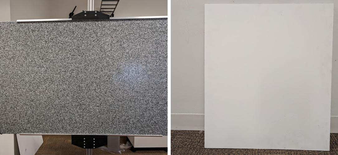
Fig. 13: Well-textured flat target (left) and white flat target (right).
In this example, typical room illumination with 200 lux was used for the passive case, whereas the projector power was set to 30mW for the active case. We compared 1. 30fps with 32ms exposure, and 2. 400fps with 2.4ms exposure and frame averaging. To minimize effects of depth quantization, the “Depth Unit” parameter in the ASIC was set to produce depth in 100μm steps, as opposed to the default 1mm steps. Note that averaging was only performed on non-zero depth values. The RMS depth error (root mean square) em [m] is normalized to subpixels ep [pixel] and is obtained as a deviation from a plane fit of 10% of the central image:
Equation 6
The experimental results are shown below.
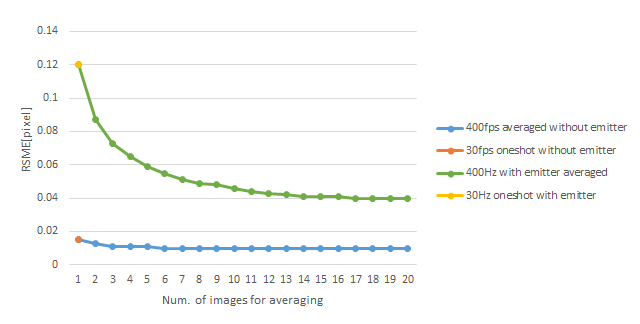
Fig. 14: Subpixel RMS error as a function of number of frames averaged. Measuring textured surfaces (no emitter, Blue curve) leads to better accuracy, and averaging does not significantly improve the results beyond 3 frames. However, for white surfaces with emitter on, the single frame accuracy starts off much worse, and experiences a significant improvement of ~3x with >10x frames of averaging, but never goes below that of the passive result.
For this experiment, a 400fps mode was available for in-house testing, but 300fps was released in official FW.
Overall, the passive results far exceed the performance of the active results. As was noted in the Projector White paper [5], this is primarily due to the much denser passive scene pattern which enables us to approach the measurement limit of the ASIC, which quantizes depth to steps of 0.032 disparities for each depth point. By contrast, the active system has a very sparse dot pattern and the projector also exhibits residual laser speckle noise and temporal fluctuations. The green curve does show the significant improvement in depth noise that is achieved by averaging frames. For example, averaging the active 400fps capture by running average of 13 frames to achieve 30fps operation reduces the RMSE subpixel depth noise from 0.12 pixels to 0.04 pixels, an improvement of 3x. This is close to the expected result assuming random noise.
4.3 Averaging vs. light level
There is a lower limit of ambient illumination where averaging frames does not help at all. This is illustrated in Figure 15, which compares the Subpixel RMS noise for single-shot 30fps vs. 11-shot 400fps capture as a function of luminance. Exposure time of each captured image was manually set to best results for each illumination condition. Maximum exposure time is 32ms at 30fps, and 2.4ms at 400fps.
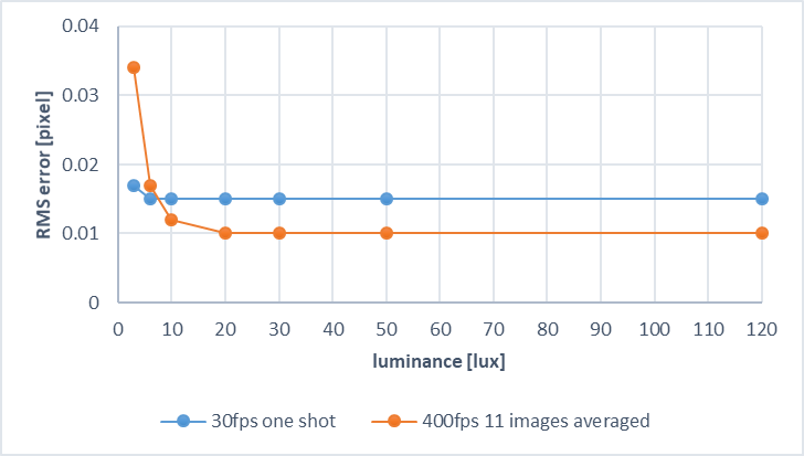
Fig. 15: RMS error with environmental luminance change
As shown in Figure 15, below 5 lux, averaging yields worse results and it is better to have longer exposures and lower frame rates that create lower noise images resulting in better depth. This is presumably due to the non-zero dark/background signal on the sensor. The induced signal must overcome this level, which for shorter exposure times becomes more difficult. Therefore, averaging many such frames no longer helps. This noise level is likely to change with choice of image sensor for different cameras.
4.4 Comparison of averaging algorithms
So far we have been recommending using the moving-average method to average depth frames. In this section we qualify that statement for high-speed capture by noting that a standard moving-average (for non-zero values) will actually introduce new motion artefacts, unless a depth threshold is used. To illustrate this point, we compare three different temporal filters: 1. Moving-average, 2. Median filter, and 3. IIR filter.

Fig. 16: Point cloud of captured surface and moving object above background. Simple average (left) and IIR filter (right) show false depth between surfaces, whereas the median filter (middle) shows no false-depth artifacts.
The moving average and standard IIR filters both show false-depth artefacts, between foreground and background when the object is moving, as seen in Figure 16. By contrast, the median filter performs well, and does not show intermediate depths. We note, however, that the median filter is not as good as the IIR or averaging filters at reducing depth noise on the surfaces, and it is also computationally more expensive. It also requires that multiple frames be stored in memory. This is discussed in more detail in the Post-Processing white paper [4]. In this paper we recommend using the “IIR filter with threshold” which is used in the Intel RealSense SDK 2.0. This method using the exponential averaging filter to average consecutive frame depth points if they are separated by a less than a certain threshold distance (or disparity), and therefore retains the benefit of smoothing surfaces as well as not showing the intermediate depth values near surface edges.
4.5 Latency
Another reason for wanting to capture items at a high frame rate, is it also decreases the latency of frame capture. Latency and Frame rate are completely different phenomena but are often assumed to be tightly linked. Latency is the lag time between the event happening and it being captured and registered. It can be critical to many real-time applications. For example, head-mounted depth cameras can be used to track hands in an Augmented/Virtual Reality system. High speed cameras mounted in monitors can also be used to track head and eye location to allow 3D displays to re-render the correct viewpoint. A drone flying at high speed and avoiding other moving obstacles also requires low latency. Most real-time applications benefit from extremely low latency.
So, what limits the latency? Usually it is related to memory buffers and waits in the data flow. For rolling shutter imagers, image scanline are read off as soon as scan lines have completed exposure. Global shutter imager, by contrast, buffer a whole frame before images are read off by the ASIC. The good news is that the Intel depth camera itself introduces very little latency because it has no full frame buffer, which means that images by necessity flow through the ASIC with ~100 lines of latency. This means that capturing motion for a global shutter camera should in worst case introduce a latency of a little over a single frame time. Unfortunately, this is often not the case. Other factors add to the latency. OS-dependent latency can be introduced by USB transfer, and the Intel RealSense SDK can introduce a latency, if buffers have not been properly minimized [7].
To directly measure the latency, we will look at an SDK example related to the motion-to-photon latency in a VR system that involves multiple steps: 1. Update Image, 2. Display on monitor, 3. Capture with camera, 4. Understand motion, and repeat. We used the rs-latency-tool from the Intel RealSense SDK 2.0 [6], as shown in Figure 17. In this experiment, the D435 is pointed at a monitor that displays time stamped images as binary dot patterns on each image. The monitor used was a 120Hz laptop monitor. This system has many contributions to the latency. The GPU adds latency in displaying an image, and the LCD screen has refresh rate and LCD limitations, and USB data packet transport introduces latency. Even though this experiment does not allow us to parse out the latency of the depth camera directly, it does provide a system-level upper limit, and it allows us to look at the effect of frame rate on latency. The results in Table 4 captured for a Windows 10 system, clearly shows that the faster the framerate, the shorter the latency. The 30fps mode exhibits a latency of 95ms, while the 400fps mode achieves 25ms, which is an improvement of ~3x. While we cannot measure the Depth Camera latency directly here, we expect it to be closer to the frame time of 2.5ms.
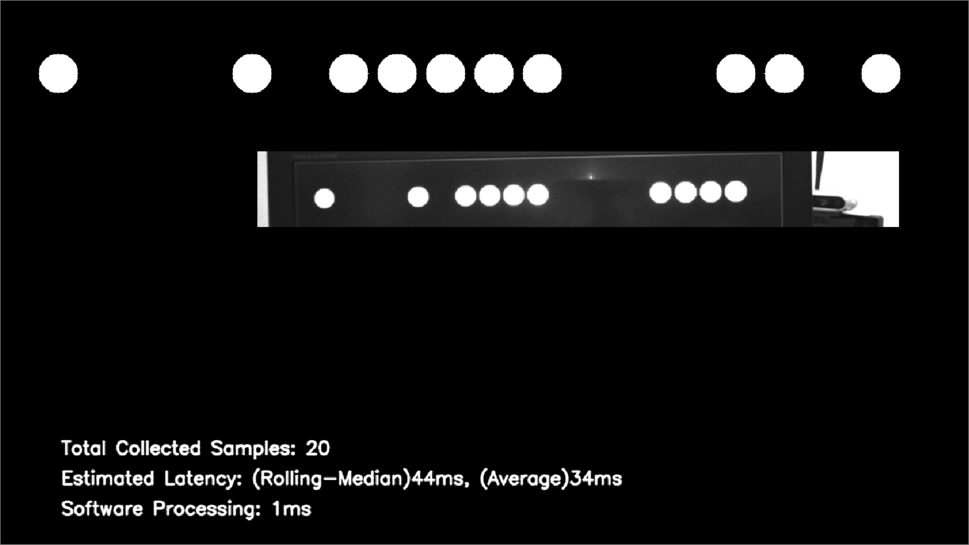
Fig. 17: Screen shot of rs-latency-tool. By detecting white circles as binary numbers, the displayed frame time is decoded. In this experiment 848x100 resolution mode was used.
| Resolution and FPS | Average [ms] |
|---|---|
| 848x100 15fps 848x100 30fps 848x100 60fps 848x100 90fps 848x100 400fps | 127 95 47 39 25 |
Table 4: Measured latencies of each frame rate. Overall, the faster the framerate, the shorter the latency.
5. Summary
We have described in this white paper how it is possible to enable and utilize a new high-speed capture mode in the Intel RealSense D435 depth camera. The high-speed capture mode is shown to trade off vertical FOV for frame rate. With a 848x100 300fps resolution mode, it is possible to track fast moving objects or to improve depth accuracy through temporal averaging of multiple frames. Both of these benefits are explored in detail. When tracking fast-moving objects, it is shown that it is important to note that the movement per frame depends on the speed of motion as well as the size of the target object and the measurement distance. For the depth accuracy improvement, the accuracy is shown that the depth is more robust to motion when the patterned projector is turned on. Without emitter, measurement accuracy was shown to depend on environment light levels, with 20lux being necessary in order to see a benefit from the higher frame rate capture. Finally, we showed that both a temporal median filter and an edge-preserving modified IIR filter, available in the Intel RealSense SDK, could be used to improve depth by about 3x.
6. References
[1] Intel RealSense website: https://www.intelrealsense.com/developers/
[2] Recommended light levels: https://www.noao.edu/education/QLTkit/ACTIVITY_Documents/Safety/LightLevels_outdoor+indoor.pdf
[3] Rolling shutter: https://en.wikipedia.org/wiki/Rolling_shutter
[4] Depth Post Processing White Paper: https://www.intel.com/content/www/us/en/support/articles/000028866/emerging-technologies/intel-realsense-technology.html
[5] Projectors for D400 Series Depth Cameras: https://www.intelrealsense.com/wp-content/uploads/2019/03/WhitePaper_on_Projectors_for_RealSense_D4xx_1.0.pdf
[6] rs-latency-tool: https://github.com/IntelRealSense/librealsense/tree/master/wrappers/opencv/latency-tool
[7] https://github.com/IntelRealSense/librealsense/wiki/Frame-Buffering-Management-in-RealSense-SDK-2.0
Updated over 2 years ago
