Tuning depth cameras for best performance
Authors: Anders Grunnet-Jepsen, John N. Sweetser, John Woodfill.
Revision 2.0
This article is also available in PDF format.
We present here a list of items that can be used to become familiar with, when trying to “tune” the Intel RealSense D415 and D435 Depth Cameras for best performance. It is not meant to be exhaustive. It is also not a tutorial on depth sensors. It is a check-list to refer to when getting started.
Start by operating at optimal depth resolution for the camera
- Intel RealSense D415: 1280x720
- Intel RealSense D435: 848x480
- Lower resolutions can be used but will degrade the depth precision. Stereo depth sensors derive their depth ranging performance from the ability to match positions of objects in the left and right images. The higher the input resolution, the better the input image, the better the depth precision.
- If a lower resolution is required for the application for computational reasons, we recommend using post-processing algorithms to immediately subsample (decimate) the higher resolution depth map and color image AFTER the data has been received. The only compelling reason to set the D4xx cameras into a lower resolution mode would be to
- Reduce the minimum operating range, which will scale with the x-y resolution,
- Reduce the bandwidth on the USB3.0 bus, to allow, for example, more cameras to operate at the same time, if the bandwidth limit has been reached.
Make sure image is properly exposed
- Check whether auto-exposure works well, or switch to manual exposure to make sure you have good color or monochrome left and right images. Poor exposure is the number one reason for bad performance.

Example: Good

Example: Bad (under exposed)
- Normally, we recommend adjusting EXPOSURE first for best results, while keeping the GAIN=16 (lowest setting). Increasing the gain tends to introduce electronic noise and, while the color image may look better, the depth quality will degrade. The exposure units are microseconds, so 33000 is 33ms. Note that overexposing the images can be just as bad as under-exposing them, so be careful to find the right exposure.
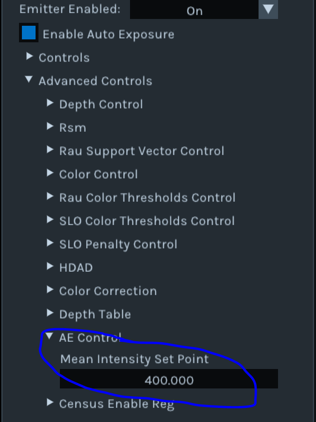
- There are two other options to consider when using the autoexposure feature. When Autoexposure is turned on, it will average the intensity of all the pixels inside of a predefined Region-Of-Interest (ROI) and will try to maintain this value at a predefined Setpoint. Both the ROI and the Setpoint can be set in software. In the Intel RealSense Viewer the
setpointcan be found under the Advanced Controls/AE Control.
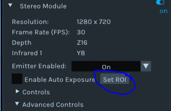
The ROI can also be set in the Intel RealSense Viewer, but will only appear after streaming has been turn on. (Ensure upper right switch is on). You will then be able to drag a ROI on the image. Corresponding software controls calls exist in the Intel RealSense SDK 2.0 of course.
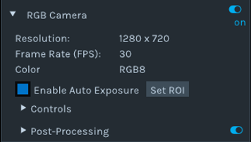
Note: The RGB ROI needs to be set separately, as shown below. While this does not impact the depth quality, it does impact the color image quality.
Verify performance regularly on a flat wall or target
- Test on White wall: Turn on projector and adjust laser power. We recommend using the nominal 150mW, but adjust it up or down for better results. For example, if you see localized laser point saturation, reduce laser power; if depth is sparse, try increasing laser power.
- Test on Textured wall: This is the best way to verify performance. Use an Intel recommended target like the one shown below. These can be downloaded here. The pattern may be projected onto the wall or printed and attached to a flat, rigid surface. Turn OFF the projector. Point to the wall and measure the RMS error of a plane-fit. The Intel RealSense Depth Quality Tool will provide metrics including the RMS error. This specific pattern was generated to show texture at many different scales, so should work across a fairly large range of distances. A well-calibrated camera should produce a Subpixel RMS error of less than 0.1.

- Recalibrate: If the flat target test shows a degradation in performance, then it may be necessary to recalibrate the camera. For example, if the RMS error is > ~0.2 pixels over the central ROI, then recalibration may be needed, especially if other aspects of performance, such as fill rate or accuracy, appear degraded as well. There is a dynamic calibration tool that can be downloaded from https://dev.intelrealsense.com/docs/calibration, or you can run the On-Chip Self-Calibration using Intel RealSense Viewer (more details at https://www.intelrealsense.com/self-calibration-for-depth-cameras).
- Read Depth Quality white paper: We also created a separate white paper that can be found here: https://dev.intelrealsense.com/docs/camera-depth-testing-methodology .
- Understand theoretical limit: Use the following equation to understand the theoretical limitation for the RMS depth error. Note that in general you should see this on the well textured target. The RMS error represents the depth noise for a localized plane fit to the depth values:
For a well-textured target you can expect to see Subpixel < 0.1 and even approaching 0.05. In general you should see ~30% smaller Subpixel with the laser turned off.
The depth noise tends to manifest itself as bumps on a plane, looking a bit like en egg carton. This is expected.
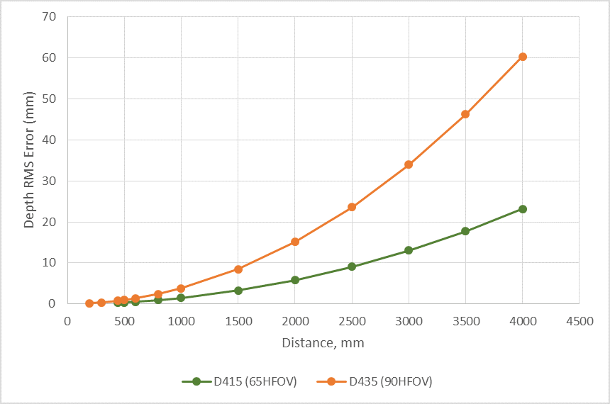
The following curve is obtained using:
- D415 with HFOV=65deg, Xres=1280, and baseline=55mm,
- D435 with HFOV=90deg, Xres=848, and baseline=50mm.
Both are for subpixel=0.08.
Play with depth setting
- The depth calculations in the D4 VPU are influenced by over 40 different parameters (exposed in the “Advanced Mode” api). We have 5+ different “depth presets”, or configurations, we recommend trying. The default setting that is in the D4 VPU works well for general use, but the “High Density” will give you better fill factor, i.e. fewer holes. This is good for usages like depth enhanced photography, but is also great for most general use.
- The “High Accuracy” preset will impose stricter criteria, and will only provide those depth values that are generated with very high confidence. This will give a less dense depth map in general but is very good for autonomous robots where false depth, aka. Hallucinations, are much worse than no depth. To illustrate this point, imagine that you are making a robot that needs to walk across lava. The robot will need to know with 100% accuracy that it is stepping on protruding solid rock, or the effects will be disastrous. Of course the extreme case is that we are too conservative on depth, and the robot does not see a real obstacle that is in front of it, but the recommended settings should be good.
- For more information on Depth Presets, and pictures for each, please refer to this:
https://github.com/IntelRealSense/librealsense/wiki/D400-Series-Visual-Presets
We do want to emphasize that the D4 VPU depth algorithm is controlled by many different parameters. Intel has provided a set of parameter options called “Depth Presets” that can be used. In the open source spirit, we do allow direct access to these parameters. However, given that there is a complex interplay between all parameters, we currently use machine learning to globally optimize for different usages. For this reason we do not plan on providing any future descriptions of “what each parameter does”.
Move as close as possible
- Intel RealSense D400 depth cameras give most precise depth ranging data for objects that are near. The depth error scales as the square of the distance away. So where at all possible, try to get as close to the object as possible, but not so close that you are within the minimum operating distance, the MinZ.

Looking at Slanted Plane: “MinZ Noise” can be reduced using depth settings. LEFT= “High Density”, RIGHT=“High Accuracy” preset
- If MinZ becomes an issue (meaning you need to get closer than MinZ), you can reduce this by reducing the Resolution of the Depth imagers. The minZ will scale linearly with the X-resolution of the depth sensors. Note that for the D415 at 1280x720 the MinZ is ~43.8cm, while for D435 at 848x480 the MinZ is ~16.8cm. The formula is:
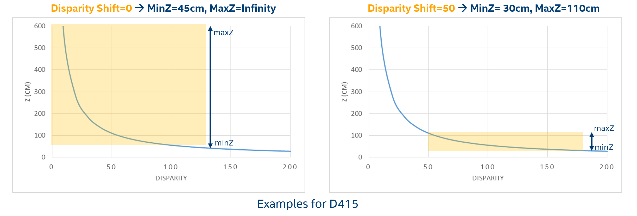
- An alternative approach to reducing the minZ is to use the “Disparity shift” parameter in the advanced mode api. Normally the depth sensor is set to generate depth for objects at distances ranging from minZ-to-infinity. By increasing the disparity shift from 0 to 128, for example, you will be able to shift that range to a NewMinZ-to-NewMaxZ. We normally only recommend doing this when it is known that there will be no objects farther away than MaxZ, such as having a depth camera mounted above a table pointing down at the table surface. Note that, because of the inverse relationship between disparity and depth, MaxZ will decrease much faster than minZ as the disparity shift is increased. Therefore, it is advised to not use a larger than necessary disparity shift. For example, if using a disparity shift of 128 then the newMaxZ is roughly equal to the original MinZ and the newMinZ is roughly equal to half of the original MinZ. Note that the tradeoff in reducing the MinZ this way is that objects at distances farther away than MaxZ will not be seen.
Use multiple depth cameras
- If field-of-view, FOV, of the cameras becomes an issue for the simultaneous capture of depth of a whole scene, then consider using multiple depth cameras to provide extended coverage.
- Intel RealSense D4xx cameras do not interfere with each other. The API provides timestamps and frame counters, but if you need Hardware sync to within a few microseconds (i.e. sub-frame time), then it is also possible to link the cameras together via an external sync cable and tell one to be master and the others to be slave. (See separate white paper on this).
- The best way to use multiple depth cameras is to treat each one independently with its own capture and processing thread, and then combine them AFTER calculating their pointclouds.
Use post-processing
By default we do not do any post-processing of the depth and instead leave this to higher level apps. We have added some simple post-processing options in the Intel RealSense SDK 2.0, but they are not meant to be exhaustive. In general we recommend applying some of the following post-processing steps:
- Sub-sampling: Do intelligent sub-sampling. We usually recommend doing a non-zero mean for a pixel and its neighbors. All stereo algorithms do involve some convolution operations, so reducing the (X, Y) resolution after capture is usually very beneficial for reducing the required compute for higher-level apps. A factor of 2 reduction in resolution will speed subsequent processing up by 4x, and a scale factor of 4 will decrease compute by 16x. Moreover, the subsampling can be used to do some rudimentary hole filling and smoothing of data using either a non-zero mean or non-zero median function. Finally, sub-sampling actually tends to help with the visualization of the point-cloud as well.
- Temporal filtering: Whenever possible, use some amount of time averaging to improve the depth, making sure not to take “holes” (depth=0) into account. There is temporal noise in the depth data. We recommend using an IIR filter. In some cases it may also be beneficial to use “persistence”, where the last valid value is retained indefinitely or within a certain time frame.
- Edge-preserving filtering: This will smooth the depth noise, retain edges while making surfaces flatter. However, again care should be taken to use parameters that do not over-aggressively remove features. We recommend doing this processing in the disparity domain (i.e. the depth scale is 1/distance), and experimenting by gradually increasing the step size threshold until it looks best for the intended usage. Another successful post-processing technique is to use a Domain-Transform filter guided by the RGB image or a bilinear filter. This can help sharpen up edges for example.
- Hole-filling: Some applications are intolerant of holes in the depth. For example, for depth-enhanced photography it is important to have depth values for every pixel, even if it is a guess. For this, it becomes necessary to fill in the holes with best guesses based on neighboring values, or the RGB image.
Change the depth step-size
- It may be necessary to change the “Depth Units” in the advanced mode api. By default the D4 VPU provides 16bit depth with a depth unit of 1000um (1mm). This means the max range will be ~65m. However, by changing this to 5000um, for example, it will be possible to report depth to a max value of 5x65= 325m.
- Alternatively, when operating at very close range, the Intel RealSense D4xx cameras can inherently deliver depth resolution well below 1mm. To avoid quantization effects, it then becomes necessary to reduce the depth unit to 100um, and the max range will be ~6.5m.
- While it is possible to get depth for really close objects by using disparity shift reducing the X-resolution and reducing the depth units, there will be other factors that will ultimately limit near-range performance. The Intel RealSense D4xx cameras are currently focused at 50cm to infinity, so will start to go out of focus well below 20cm. Also, for really near objects that are not flat, like a wall, the views from the left and right cameras may be different at really close range and will therefore not give any depth range. To understand this, think of moving your index finger close to your eyes. At some point your left eye and right eye will actually see the opposite sides of the finger, so it will not be possible to do stereo matching at all.
Use external projector
- While the internal projector is very good (shown below), it is really quite low power and is not designed to illuminate very large rooms. It is therefore sometimes beneficial to add one or more additional external projectors. The D4xx camera will benefit from any additional texture projected onto a scene that has no inherent texture, like a flat white wall. Ordinarily, no tuning needs to be done in the D4 VPU when you use any external projectors as long as it is on continuously or flickering at >50KHz, so as not to interfere with the rolling shutter or auto-exposure properties of the sensor.

- External projectors can be really good in fixed installations where low power consumption is not critical, like a static box measurement device. It is also good for illuminating objects that are far away, by adding illumination nearer to the object.
- Regarding the specific projection pattern, we recommend somewhere between 5000 and 300,000 semi-random dots. We normally recommend patterns that are scale invariant. This means that if the separation between the projector and the depth sensor changes, then the depth sensor will still see texture across a large range of distances.
- It is possible to use light in visible or near-infrared (ranging from ~400-1000nm), although we normally recommend 850nm as being a good compromise in being invisible to the human eye while still being visible to the IR sensor with about 15-40% reduction in sensitivity, depending on the sensor used.
- When using a laser-based projector, it is extremely important to take all means necessary to reduce the laser-speckle or it will adversely affect the depth. Non-coherent light sources will lead to best results in terms of depth noise, but cannot normally generate as high contrast pattern at long range. Even when all speckle reduction methods are employed it is not uncommon to see a passive target or LED projector give >30% better depth than a laser-based projector.
- Projectors do not need to be co-located with the depth sensor. It is also acceptable to move or shake the projector if desired, but it is not needed.
- Make sure the projector is eye-safe.
Use the left-color camera
- While the D415 and D435 camera both have a built-in 3rd color camera that is processed through an ISP to give good color independent of the depth, there are many reasons to use the left camera of the stereo pair instead (or in addition).
- The “LEFT IR” camera has the benefit of always 1. Being pixel-perfect aligned, calibrated, and overlapped with the depth map, 2. Perfectly time-synchronized, 3. Requires no additional computational overhead to align color-to-depth, and 4. Gives no additional occlusion artifacts, because it is exactly co-aligned. The main draw-back is that it will normally show the projector pattern if the projector is turned on.
- The D415 uses color sensors for depth, whereas the D435 use monochrome sensors. One very nice patented feature of the D415, is that the Depth D4 VPU has the ability to do a rudimentary removal of the IR projection pattern, at no additional CPU or power cost. This only works for the D415 at 1280x720 resolution. It is based on changing the color correction matrix in the Advanced Mode API to the following 12 values. Note that the laser has not been turned off so the depth is not impacted at all. However, the green colors are reduced.
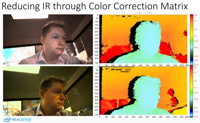

ColorCorrection={0.520508, 1.99023, 1.50684, -2, -2, -0.0820312, 1.12305, 1.01367, 1.69824, -2, 0.575195, -0.411133. The function api is in rs_advanced_mode.h:
/* Sets new values for STColorCorrection, returns 0 if success */
void rs2_set_color_correction(rs2_device* dev, const  STColorCorrection* group, rs2_error** error);
This is especially helpful when scanning 3D objects because it will allows you to employ visual odometry and tracking that will not be impacted by the IR pattern that will move with the camera.
Choose the best camera for the job
1.We currently have two camera models, the Intel RealSense D415 and D435, and they represent two design points in a vast design space, including field-of-view, imager baseline, imager choice, projector choice, dimensions, cost, power, and so on.

- The main difference betwee n the D415 and D435 is that the D415 has a ~64 degree Horizontal field-of-view (HFOV) while the D435 has ~86 degree HFOV. The latter also uses global shutter imagers instead of the rolling shutter imagers in the former. Another difference is that the D415 has Left+Right imagers, emitters and RGB sensor all on one stiffener, making calibration an order of magnitude more robust for the 3rd color imager. The D435 camera is based on the D430 module and uses a separate RGB camera attached to a separate stiffener. This choice was based on feedback from previous generations of cameras and modules where some customers wanted the flexibility to choose whatever RGB camera they wanted. Another difference is the D415 uses 2x 2 megapixel imagers (OV2740) with a baseline of 55mm. The D435 are 2x 1 megapixel (OV9282) with a baseline of 50mm.
| Parameter | D415 Camera properties | D435 Camera properties |
|---|---|---|
| Image Sensor | OV2740 | OV9282 |
| Active Pixels | 1920 × 1080 | 1280 × 800 |
| Sensor Aspect Ratio | 16:9 | 8:5 |
| Format | 10-bit RAW | 10-bit RAW |
| F Number | f/2.0 | f/2.0 |
| Focal Length | 1.88 mm | 1.93 mm |
| Filter Type | IR Cut – D400, None – D410 | None |
| Focus | Fixed | Fixed |
| Shutter Type | Rolling Shutter | Global Shutter |
| Signal Interface | MIPI CSI-2, 2X Lanes | MIPI CSI-2, 2X Lanes |
| Horizontal Field of View | 69.4 | 91.2 |
| Vertical Field of View | 42.5 | 65.5 |
| Diagonal Field of View | 77 | 100.6 |
| Distortion | <=1.5% | <=1.5% |
- Due to the wider FOV, the smaller baseline, and the smaller sensor resolution, the D435 has more depth noise (>2x) at any given range, compared to the D415. The D435 does however, benefit from having smaller minimum operation distance (minZ) at the same resolution. This means you can get closer to objects. For example, at 848x480 the D415 has a minZ of about 31cm, whereas the D435 has a minZ of about 19.5cm.
Change Background
While many applications do not allow for changing the environment, some usages do. For example if the purpose is to examine parcels placed on a desk, it would greatly help the measurements if the desktop had a matt textured pattern, like the one shown above in 3b. This is preferable to a white glossy background, like a white tabletop.
Change IR filter or background illumination
- Both the Intel RealSense D415 and D435 see all light in the visible and IR. The reason for this is that the Intel RealSense vision processor D4 VPU does a very good job of extracting depth from purely passive scenes, without any projector and actually benefits from using Red, Green, Blue images. However, if the purpose is to see white walls indoors at a long distance, it may be necessary to enhance the SNR of the projected laser pattern. This can of course be accomplished by increasing the laser power, but it can also be done by placing an IR-bandpass filter in front of the Left+Right imager. To determine whether this will improve your performance, you can try to turn off all the lights instead while leaving the projector on, as this will effectively emulate the performance you will see with the IR filter on. The “white wall” range can increase from ~3m to 10m this way.
- When placing any optical windows or filters in front of the Intel RealSense D4xx cameras, it is important to make sure that no laser light from the projector reflects back into the imagers as this will adversely affect the depth. We recommend using separate windows for the left and right imagers.
Avoid Repetitive structures
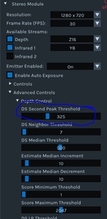
- Stereo depth computation depends on determining matches between left and right images. If there are repetitive structures in the scene, like fences or wire-grids, this determination can become ambiguous. One of the tools we have for determining confidence is the advanced API setting “DSSecondPeakThreshold.” The Intel RealSense D4 VPU determines match scores for both the best match as well as the second best match – if the best match is of similar quality to the second best match, then it may well occur due to aliasing resulting from repetitive structures – how different the two matches need to be is determined by the “DSSecondPeakThreshold” parameter. By increasing its value, more depth results will appear as black, or zero, reducing the number of matches resulting from aliasing.
- Another mitigation strategy that may help is to tilt the camera a few degrees (e.g., 20-30 deg) from the horizontal.
Use Sunlight, but avoid glare
- Most depth cameras degrade dramatically in sunlight. By contrast, both the Intel RealSense D415 and D435 tend to perform even better in bright light. The way to understand this is that the depth quality in the Intel RealSense D4xx is directly related to the quality of the input images. It is well known that small cell phone cameras (and the ones used in the Intel RealSense D4xx series) give poor quality grainy images under low light conditions, but provide excellent images in bright sunlight. Sunlight reduces the sensor noise and tend to “brings out” the texture in objects. Moreover, the exposure can be reduced to near 1ms which reduces motion artifacts as well. So the upshot is that the Intel RealSense D4xx cameras actually perform very well in sunlight.
- One issue to be careful about is lens glare when pointing at or near the sun. It is recommended that the lenses are shielded by baffles to reduce the risk of lens glares.
- When operating an Intel RealSense D4xx camera outside, it is important to be especially careful in regards to the auto-exposure, especially if the sun or reflections of sun are visible in the image. By default the auto-exposure algorithm tries to keep the average intensity of the whole image within a certain range. If the sun is in that image, everything else will suddenly become black. For many applications, like autonomous robots or cars, it helps to simply change the Region-of-interest of the auto-exposure algorithm to a smaller size, or specifically to the lower half of the image.
Updated over 2 years ago
