Depth Map Improvements for Stereo-based Depth Cameras on Drones
by Sergey Dorodnicov, Daniel Pohl and Markus Achtelik
This article is also available in PDF format.
Abstract—Using stereo-based depth cameras outdoors on drones can lead to challenging situations for stereo algorithms calculating a depth map. A false depth value indicating an object close to the drone can confuse obstacle avoidance algorithms and lead to erratic behavior during the drone flight. We analyze the encountered issues from real-world tests together with practical solutions including a post-processing method to modify depth maps against outliers with wrong depth values. Index Terms—depth camera, stereo, computer vision.
I. INTRODUCTION ##
In the last decade, depth cameras have become available in more affordable versions which increased the usage both in the industrial as well as in the consumer space. One interesting use case is on drones, where stereo-based depth cameras generate data for obstacle avoidance algorithms to keep the drone safe. However, the algorithms used to calculate depth information are trying to solve an under-determined problem. From two-dimensional images, data in three dimensions is reconstructed. Therefore, it seems only natural that in certain cases the generated depth images might contain wrong data as shown in Figure 1. Specifically, when used in larger outdoor environments at different weather conditions like drones would exhibit, the set of parameters and requirements might be very different from other common use cases for depth sensors as found in indoor scenarios like finger tracking or gesture recognition.
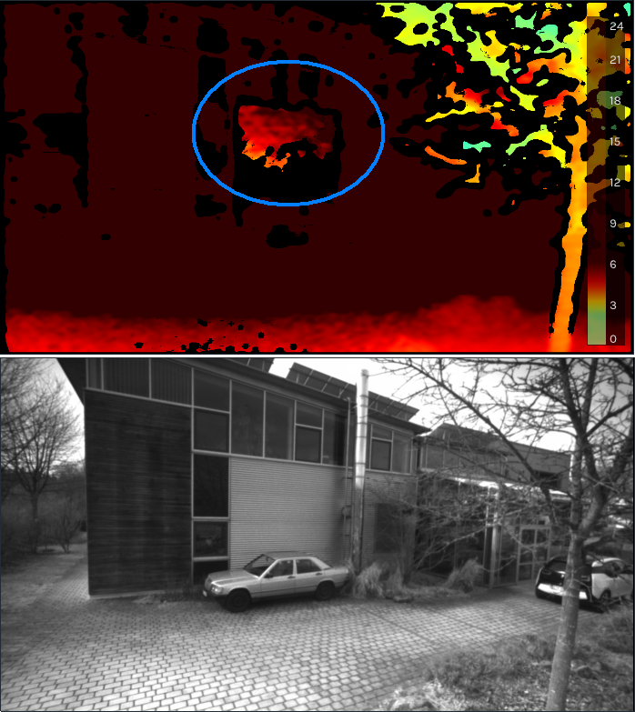
Figure 1. The top image shows the depth map from the scene at the bottom. The colors are applied depending on the distance in meters as shown in the scale on the right part of the image. At the light gray wall with thin horizontal stripes, the algorithm of the depth sensor wrongly estimates an object close to the camera.
In this paper, we present the encountered challenges of using depth cameras on drones and how we overcame them.
Our contributions are:
- Description of stereo camera issues on drones
- Solutions to minimize the encountered problems
- Release of the solutions as highly optimized open source code
In the following, we will first give an overview of related work in the space of drones with different depth cameras. Next, we describe the use case of the depth sensor on our drone and issues observed for enabling automatic obstacle avoidance. After specifying the hardware and software system, we take a look at incorrect depth values from the used depth cameras. Having all of this laid out, we provide improvements against depth outliers through a variety of methods like calibration, depth camera settings and post-processing methods.
We compare the results of the post-processing steps and provide a performance analysis of the used algorithms. We discuss current limitations and give an outlook on further improvements. Last, we conclude and link to our open source implementation.
II. RELATED WORK##
There are various devices to measure depth to other objects. Options which have also been used on drones include ultrasonic [1], lidar [2], [3], radar [4] or depth camera-based systems [5]–[8]. While all of these have their advantages and drawbacks, we focus in this work on depth camera-based systems due to their light weight, detailed depth information and relatively low cost.
In the category of depth cameras, we describe two very common types and their differences [9].
Time Of Flight (TOF) cameras: a laser or LED is used to illuminate where the camera is pointing at [10]. As the constant speed of light is known, the round-trip time of such a light signal returning to the camera sensor can be used to calculate an approximate distance. Common advantages of these depth sensors are simplicity, efficient distance algorithm and their speed. Their drawbacks show in bright outdoor usage where the background light might interfere with measurements, potential interference with other TOF devices and issues at reflections.
Stereo-based depth sensors: these devices are taking two images with a fixed, known offset between the two image cameras. Using stereo matching algorithms [11], [12] together with the known intrinsic and extrinsic parameters of the camera, they can generate approximate depth values for the image. Usually, these sensors consume less power compared to TOF cameras.
III. DRONE USE CASE##
To avoid accidents, injuries and crashes, it is very important for drones to avoid flying into obstacles. Depth cameras help the drone to "see" the environment. The obstacle avoidance algorithms that we use are taking the depth image from one or more depth cameras. As we know the mounted camera position and orientation on the drone and the GPS location of the drone, we transform the data from the depth image into world space. We map those depth values to 3D voxel locations. For the voxel value, we update the probability of that space to be occupied. Having the voxel map available, we check the drone’s heading and velocity against potential obstacles in that direction. If we find any, we redirect to avoid a collision.
As we found in real-world usage of drones with depth sensors, there are sometimes issues that the depth values are not correct and can therefore lead to problems. For example, suddenly, a wrong, very close depth value appears in front of the drone. This might be interpreted as an obstacle to which our safety distance is not kept and strongly violated. A common reaction might be to move the drone quickly away from that obstacle or to at least not move further into the direction of the obstacle. For a drone operator on the ground observing what happens in the sky, such behavior of the drone is not comprehensive. The operator sees that there is no obstacle, yet the drone behaves in an undesired way trying to avoid invisible objects.
IV. SYSTEM##
In the following scenarios, we use the Intel® NUC7i7BNH platform with the Intel® Core i7-7567U (2 cores, 4 threads) at a base frequency of 3.5 GHz with 16 GB memory. Given the requirements of being able to work outside in bright environments and the goal of having a low power consumption, we decided to use a stereo-based depth sensor. The model is Intel® RealSense™ [13] D435i with the firmware 5.11.6.250.
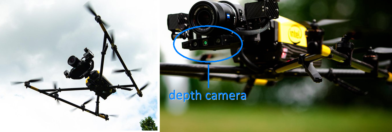
Figure 2. Drone with depth sensor
The system runs Ubuntu 18.04 with the Intel RealSense SDK 2.0 (build 2.23.0). Some of the visualizations are generated with the RealSense Viewer 2.23.0. For image operations, we use OpenCV 3.4.5. The depth camera is mounted on an Intel Falcon 8+ octocopter (Figure 2). We use a camera resolution of 848×480 pixels at 30 frames per second.
V. INCORRECT DEPTH VALUES##
As mentioned in Section III, we discovered some cases in which depth values in the depth map were not accurate and disturb the obstacle avoidance algorithms. Figure 1 shows one example. We provide another case in Figure 3.
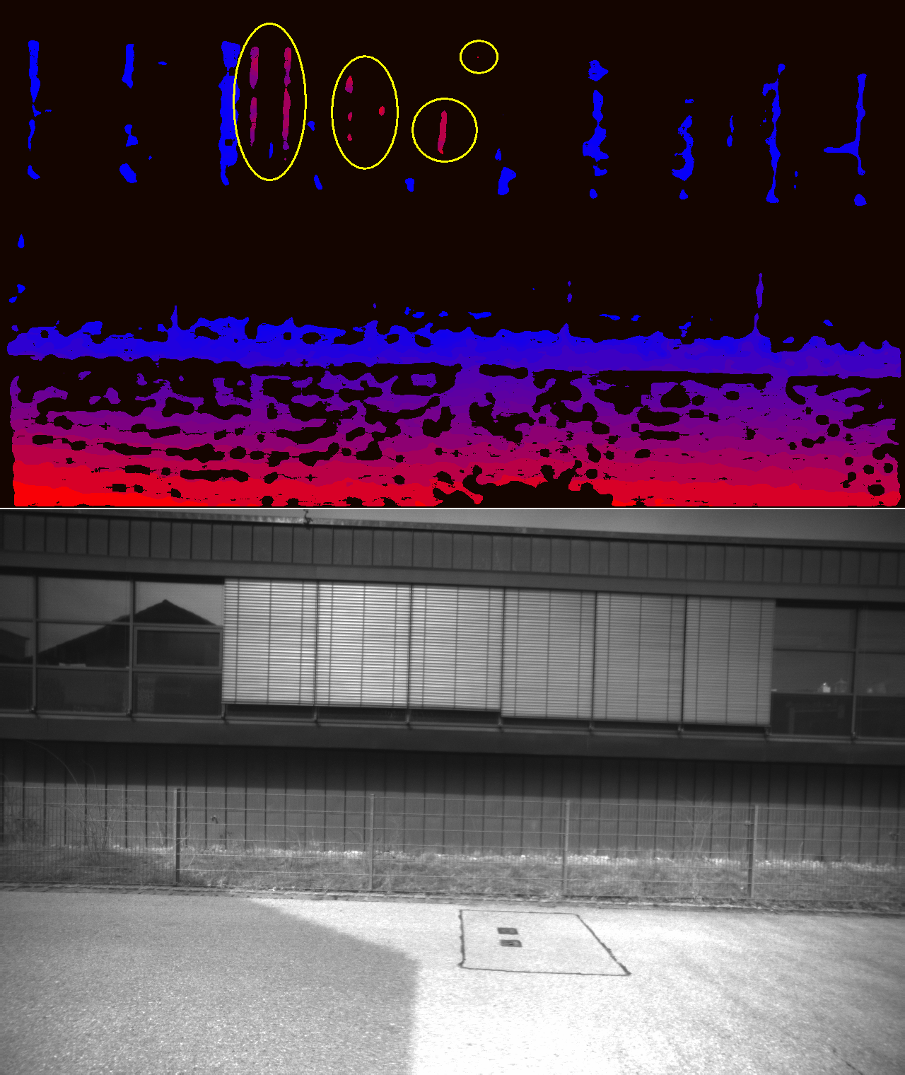
Figure 3. A case in which parts of the blinds on the windows are wrongly indicating depth which is very close to the camera. Near distances are represented in an intense red, while the farther away it gets, the coloring changes to blue.
Both cases have in common that there is a structure with repetitive content which can easily disturb stereo feature matching as almost the same color values are frequently repeated in neighboring areas.
VI. IMPROVEMENTS##
In this section, we provide improvements for the previously described depth maps with some incorrect depth values.
A. Calibration###
Depth cameras are shipped with a previously executed factory calibration. Due to the stress on the modules endured by a potential air freight delivery with different pressure conditions at such high altitudes and potential shaking during transportation, it can happen that physical properties of the device slightly differ from the state it was during calibration.
At least in one case we found significant improvements when running a local calibration on the device. As test setup, we used a carpet intended for children to play with small toy vehicles on it. The carpet provides strong features which can be picked up by the stereo algorithm. For this test, we used very strict camera settings which rejected depth values if their confidence was not extremely high.
For the Intel RealSense D435i camera, there are tools that allow a recalibration within a few minutes. As shown in Figure 4, this can increase the confidence in depth values and therefore provide more valid inputs. In most real-world cases the differences will not be as high as illustrated here, but this shows how important an accurate camera calibration is.
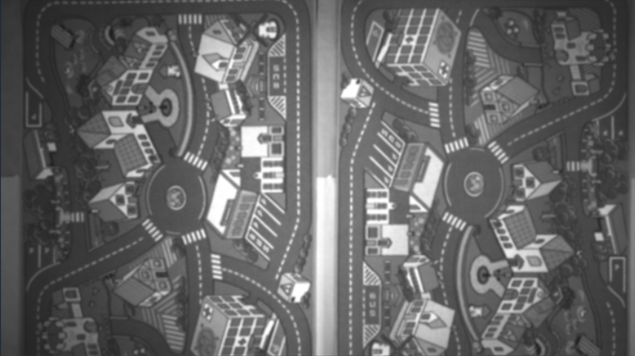
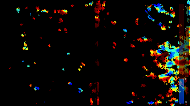
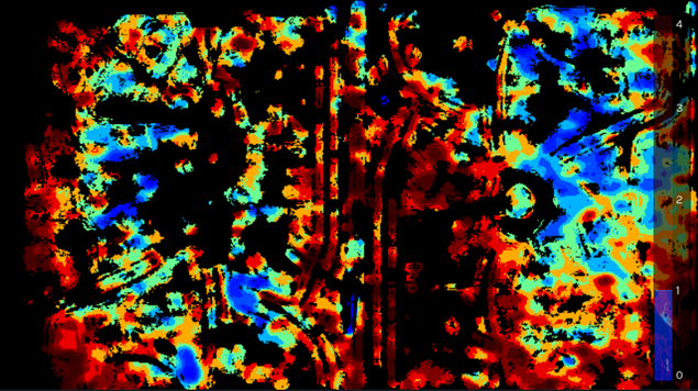
Figure 4. The top gray scale image shows the carpet for toys as target in a test setup. The middle image shows the depth values before manual calibration with camera settings for very high confidence of depth values. The bottom image shows the depth values after recalibration.
B. Depth Camera Settings###
As a guideline for outdoor depth sensing as used on drones, we prefer having fewer depth values at a high confidence compared to receiving many values which are less certain to be valid. In the RealSense D435i camera, there are various settings affecting this which can be modified through visual tools like the RealSense Viewer and can be stored in .json files. Those configuration files can be uploaded in the application via API calls. We describe the most relevant changes in the settings that we made compared to the default. To give a better understanding of the parameters on the resulting images, we show different settings in the Appendix.
texturecountthresh, texturedifferencethresh: These settings describe how much difference in intensity in the gray scale stereo image needs to be to determine a valid feature. In outdoor usage, the sky and clouds provide an almost similar color with only small deviations. Walls captured during inspection flights might have areas of the same color which do not make strong features. To increase the confidence on depth values, we increased the values of texturecountthresh, which sets how many pixels of evidence of texture are required from 0 to 4 and set the value of texturedifferencethresh, how big a difference is required for evidence of texture, to 50.
secondpeakdelta: When analyzing the disparities of an area in the stereo images for a match, there might be one clear candidate indicating a large peak in terms of correlation. In some cases, multiple candidates could be viable at different peak levels. The second peak threshold determines how big the difference from another peak needs to be, in order to have confidence in the current peak being the correct one. We increased this value from a default of 645 to 775.
scanlinep1, scanlinep1onediscon, ...: For finding the best correlation form the disparities, a penalty model is used as described in [14]. In addition to estimating the validity of a current correlation, neighboring areas with their estimate are analyzed and taken into account. A small difference can be expressed in a small penalty (scanlinep1 = 30) while a larger difference leads to a second penalty value (scanlinep2 = 98). Both penalties are added together in an internal cost model for the likelihood of a correlation to be the correct one. Further fine tuning on large color or intensity differences between the left and right image can be set with scanlinep1onediscon and scanlinep1twodiscon.
medianthreshold: When looking for a peak regarding correlation, we want it to have a significantly large value to clearly differ from the median of other correlation values. While the default is set to 796, we found that we were able to lower this value safely to 625. This did not introduce any noticeable artefacts, but made more valid depth values available.
autoexposure-setpoint: The autoexposure setting can be changed to deliver a darker (lower value) or brighter image. It is set to 1500 by default. For outdoor usages, we found the brighter value of 2000 to work better. Details in the sky like clouds are not relevant for us, so if this part is overexposed, it has no negative effect. On the positive side, increasing brightness makes darker objects like the bark on a tree brighter and enables better feature detection on it. We present the full .json file with all settings in the Appendix.
C. Post-processing of Depth Images###
With a good depth camera calibration and the modified parameters, we area able to get good images with relatively high confidence features. However, for our purpose this is still not enough and cases with invalid depth values have still been observed. We tried many different other parameter settings, but in the end, we were not able to remove the outliers just through parameters without losing almost all other valid depth data. Instead, to handle the invalid depth values, we are applying post-processing steps to the received depth image. As described in [15], there are various known methods for post-processing like downsizing the image in certain ways to smooth out camera noise, applying edge-preserving filtering techniques or doing temporal filtering across multiple frames.
In our outdoor drone use case, we apply different postprocessing methods. For the ones we describe, we additionally require reading out the left rectified camera image stream which is synchronized with the depth image. In our depth camera model this image is in an 8-bit gray scale format. The pseudocode for our post-processing operations is in this listing:
const int reduceX = 4;
const int reduceY = 4;
cvResizeGrayscaleImage(reduceX, reduceY);
resizeDepthImageToMinimumInBlock(reduceX, reduceY);

// create edge mask
cvScharrX(grayImage, maskEdgeX);
cvScharrY(grayImage, maskEdgeY);

convertScaleAbsX(maskEdgeX);
convertScaleAbsY(maskEdgeY);

cvAddWeighted(maskEdgeX, maskEdgeY, maskEdge, 0.5);
cvThreshold(maskEdge, 192, 255, THRESH_BINARY);

// createcorner mask
cvHarris(grayImageFloat, maskCorners, 2, 3, 0.04);
cvThreshold(maskCorners, 300, 255, THRESH_BINARY);

// combine both masks
cvBitwiseOr(maskCombined, maskEdge, maskCorners);

// apply morphological opening
cvMorphOpen(maskCombined, MORPH_ELLIPSE(3, 3));

// use mask on depth image
depthImage.cvCopy(depthImageFinal, maskCombined);
In the lines 1-4, we are downsizing both the depth and the camera image by a factor of four in each dimension. For the depth map, we search within a 4x4 pixel block for the closest depth value which is not zero, meaning not invalid. We take this value as the downsized pixel value. The reason for this selection is that for obstacle avoidance our most important information is which object might be the closest to us. For the gray scale image, we can use regular OpenCV downsizing. In our case, nearest-neighbor downsizing was sufficient, but, depending on the performance budget, bilinear filtering might be chosen as well. After resizing, the depth image and camera image have been lowered from a resolution of 848 × 480 pixels to 242×120 pixels. With 16 times fewer pixels, further processing on the images will be much faster.
Edges and corners are very robust features for stereo matching. To achieve even higher confidence in the depth values, we want to mask out all depth values which do not have edges or corners in the corresponding area of the gray scale image. To do this, we create an image mask for edges and one for corners. For edge detection, we use the OpenCV Scharr operator [16] as shown in lines 7 and 8 of the pseudo-code listing. For the intermediate images in X and Y dimension, we apply the absolute function and convert them into an 8-bit format (line 10, 11). We add both images together and apply a binary threshold on the mask (lines 13, 14). Using the case from Figure 3, we visualize these processing steps in Figure 5.
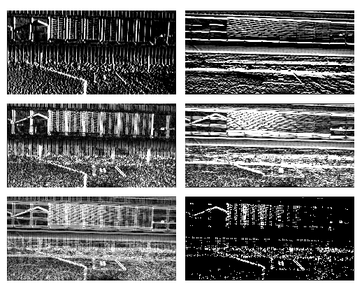
Figure 5. Steps for creating the edge mask. The top row shows the Scharr images in X and Y dimension. The second row applies the absolute function to the values from the top row. The last row shows left the added images from the middle row. On the right, it shows the final mask with the applied binary threshold function.
For creating the corner mask, we use the Harris Corner Detector [17] in OpenCV (line 17). Again, we apply a threshold in the line below. We combine the mask for edges with the mask for corners in line 21. To eliminate too small areas in the mask, we apply the morphological opening operation on the mask which applies an erosion followed by a dilation on the image (line 24). We apply the final mask to the resized depth image. Only where positive values are in the mask, the depth value will be copied into the final image, otherwise it will be set to zero, indicating no valid depth information (line 27). We visualize these steps in Figure 6.
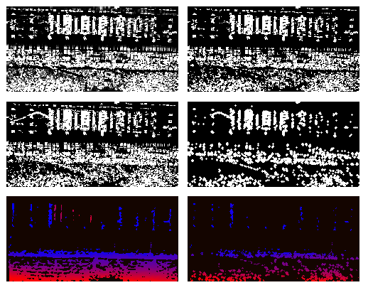
Figure 6. Steps for creating the corner mask. Top left shows the corners as detected by Harris. On the right, the binary threshold is applied to that. In the second row on the left, the combined edge and corner mask is shown. On the right side the final mask is shown after the opening function has been applied. The bottom row shows left the original, resized depth map. On the right, the mask has been applied to it. This is the final version of the depth map without outliers of wrong depth.
D. Results###
Using recalibration, tuning of the depth camera parameters and applying the post-processing steps as described, we got a much higher quality depth map as the example with the result in Figure 6 (bottom right) shows. A comparison between the before and after images with a resolution of 242×120 = 29040 pixels, is shown in Table I.
TABLE I. COMPARING THE BEFORE AND AFTER IMAGE FROM FIGURE 6 (BOTTOM). THE FIRST NUMBER INDICATES THE AMOUNT OF PIXELS IN AN IMAGE WITH A RESOLUTION OF 242×120 PIXELS. THE SECOND NUMBER SHOWS THE PERCENTAGE OF PIXELS IN THAT IMAGE.
| original | our method | |
|---|---|---|
| number of depth values | 7375 (25%) | 2802 (10%) |
| number of outliers | 94 (0.3%) | 0 (0%) |
While the image loses more than half of its valid depth information with our method, it also eliminates all outliers. As it can be seen in comparing both images, the loss happens relatively evenly across areas. For our obstacle avoidance this means that we still have enough information in these areas to be aware of potential objects in our path. To repeat the statement we made before: we prefer having fewer depth values at a high confidence compared to receiving many values which are less certain to be valid. Using our method, this goal is achieved.
We tested our method on multiple hours of log files from various drone flights. In almost all cases, we were able to filter out wrong depth measures that would have impacted the drone’s obstacle avoidance to work correctly.
E. Performance###
The post processing steps will increase the required compute load. We optimized our code to make use of AVX2 functions for our custom-written resizing function which we make available as open source. OpenCV, compiled with the right flags, will use AVX2 intrinsics for the relevant functions. We measured how much time the individual steps for post-processing took for processing 30 frames (the amount of frames we receive within one second from the depth camera) and show this in Table II.
Table II. TIME IN MS FOR POST-PROCESSING STEPS FOR 30 FRAMES.
| resize gray scale | 1.2 |
| resize depth map | 1.5 |
| create edge mask | 2.9 |
| create corner mask | 9.3 |
| combine masks | 1.8 |
| opening mask | 1.3 |
| apply mask | 0.3 |
| total | 18.3 |
VII. LIMITATIONS AND OUTLOOK##
There are still some rare cases in which wrong depth makes it through all the suggested methods. The area of pixels with wrong depth is already much smaller with our methods. To increase the robustness against these rare outliers, we recommend using the depth data in a spatial mapping like in a 3D voxel map. Popular libraries like Octomap [18] are a good starting point. Before values are entered into such a spatial structure, it might be required to have multiple positive hits for occupancy over multiple frames and/or observations of obstacles from slightly different perspectives. In the case of drones, movement is pretty common and even when holding the position, minimal movements from wind might already change what the depth camera delivers. The position of a wrong depth value and its corresponding 3D space might change by such a small movement. As the incorrect depth values are not geometrically consistent, they might be filtered out through the spatial mapping technique.
While the performance impact of our routines is already relatively low for a modern PC-based system, the overhead might still hurt performance on highly embedded systems. In future versions of depth cameras, it might be a desired step to have our described methods directly implemented in hardware.
VIII. CONCLUSION##
In this work, we described the issues of receiving wrong depth data that was observed in some drone flights outdoors. Through proper calibration, modification of internal depth camera parameters and a series of post-processing steps on the depth map, we were able to clean up almost all outliers with wrong depth. The resulting depth data can be used for robust obstacle avoidance with spatial mapping of the environment. Our highly optimized algorithms for post-processing are released as open source under librealsense/wrappers/opencv/depth-filter
REFERENCES##
[1] N. Gageik, T. Müller, and S. Montenegro, “Obstacle Detection and Collision Avoidance using Ultrasonic Distance Sensors for an Autonomous Quadrocopter”, University of Wurzburg, Aerospace information Technology Wurzburg, pp. 3–23, 2012.
[2] L. Wallace, A. Lucieer, C. Watson, and D. Turner, “Development of a UAV-LiDAR System with Application to Forest Inventory”, Remote Sensing, vol. 4, no. 6, pp. 1519–1543, 2012. DOI: 10.3390/rs4061519.
[3] A. Ferrick, J. Fish, E. Venator, and G. S. Lee, “UAV Obstacle Avoidance using Image Processing Techniques”, in IEEE International Conference on Technologies for Practical Robot Applications (TePRA), 2012, pp. 73–78. DOI: 10.1109/TePRA.2012.6215657.
[4] K. B. Ariyur, P. Lommel, and D. F. Enns, “Reactive Inflight Obstacle Avoidance via Radar Feedback”, in Proceedings of the 2005 American Control Conference, IEEE, pp. 2978–2982. DOI: 10 . 1109 / ACC . 2005 . 1470427.
[5] K Boudjit, C Larbes, and M Alouache, “Control of Flight Operation of a Quad rotor AR. Drone Using Depth Map from Microsoft Kinect Sensor”, International Journal of Engineering and Innovative Technology (IJEIT), vol. 3, pp. 15–19, 2013.
[6] A Deris, I Trigonis, A Aravanis, and E. Stathopoulou, “Depth cameras on UAVs: A first approach”, The International Archives of Photogrammetry, Remote Sensing and Spatial Information Sciences, vol. 42, p. 231, 2017. DOI: 10.5194/isprs-archives-XLII-2-W3-231-2017.
[7] I. Sa, M. Kamel, M. Burri, M. Bloesch, R. Khanna, M. Popovic, J. Nieto, and R. Siegwart, “Build Your Own Visual-Inertial Drone: A Cost-Effective and Open-Source Autonomous Drone”, IEEE Robotics & Automation Magazine, vol. 25, no. 1, pp. 89–103, 2018. DOI: 10. 1109/MRA.2017.2771326.
[8] S. Kawabata, K. Nohara, J. H. Lee, H. Suzuki, T. Takiguchi, O. S. Park, and S. Okamoto, “Autonomous Flight Drone with Depth Camera for Inspection Task of Infra Structure”, in Proceedings of the International MultiConference of Engineers and Computer Scientists, vol. 2, 2018.
[9] H. Sarbolandi, D. Lefloch, and A. Kolb, “Kinect Range Sensing: Structured-Light versus Time-of-Flight Kinect”, Computer vision and image understanding, vol. 139, pp. 1–20, 2015. DOI: 10.1016/j.cviu.2015.05.006.
[10] P. Zanuttigh, G. Marin, C. Dal Mutto, F. Dominio, L. Minto, and G. M. Cortelazzo, “Time-of-Flight and Structured Light Depth Cameras”, Technology and Applications, 2016. DOI: 10.1007/978-3-319-30973-6.
[11] S. T. Barnard and M. A. Fischler, “Computational Stereo”, 1982. DOI: 10.1145/356893.356896. [12] T. Kanade and M. Okutomi, “A Stereo Matching Algorithm with an Adaptive Window: Theory and Experiment”, in Proceedings. 1991 IEEE International Conference on Robotics and Automation, pp. 1088–1095. DOI: 10.1109/ROBOT.1991.131738.
[13] L. Keselman, J. Iselin Woodfill, A. Grunnet-Jepsen, and A. Bhowmik, “Intel RealSense Stereoscopic Depth Cameras”, in Proceedings of the IEEE Conference on Computer Vision and Pattern Recognition Workshops, 2017, pp. 1–10. DOI: 10.1109/CVPRW.2017.167.
[14] M. Michael, J. Salmen, J. Stallkamp, and M. Schlipsing, “Real-time Stereo Vision: Optimizing Semi-Global Matching”, in IEEE Intelligent Vehicles Symposium, 2013, pp. 1197–1202. DOI: 10.1109/IVS.2013.6629629.
[15] A. Grunnet-Jepsen and D. Tong, Depth Post-Processing for Intel RealSense D400 Depth Cameras.
[16] H. Scharr, “Optimale Operatoren in der digitalen Bildverarbeitung”, 2000. DOI: 10.11588/heidok.00000962.
[17] K. G. Derpanis, “The Harris Corner Detector”, York University, 2004.
[18] A. Hornung, K. M. Wurm, M. Bennewitz, C. Stachniss, and W. Burgard, “Octomap: An Efficient Probabilistic 3D Mapping Framework Based on Octrees”, Autonomous robots, vol. 34, no. 3, pp. 189–206, 2013. DOI: 10.1007/ s10514-012-9321-0.
APPENDIX##
To give a better overview of the impact of changing some of the mentioned RealSense depth camera parameters, we provide examples of the resulting images from Figure 7 to Figure 11. In order to find the best matching values, this was tested and finetuned on various environments: natural, industrial, residential and mixtures of those. The height was varied between looking at objects almost at the same height and from a much higher perspective, e.g. 30 to 50 meters above ground. When testing different parameters on the ground, we recommend using the Intel RealSense Viewer in which the parameters can be changed in real-time through sliders to directly see the impact on the images.

Figure 7. Gray scale images with different auto exposure values: 1500, 2000 (ours), 2500.

Figure 8. Depth images with different secondpeakdelta values: 400, 645, 775 (ours)

Figure 9. Depth images with different penalty values (scanlinep2onediscon): 50, 105 (ours), 235.

Figure 10. Depth images with different values for texturecountthresh and texturedifferencethresh: (0, 0), (4, 50) (ours), (8, 100).

Figure 11. Depth images with different values for medianthreshold: 500, 625 (ours), 796.
The following is the text for the .json file that can be loaded in Intel RealSense tools and API calls to configure the cameras as described in the paper.
"aux-param-autoexposure-setpoint": "2000",
"aux-param-colorcorrection1": "0.298828",
"aux-param-colorcorrection10": "0",
"aux-param-colorcorrection11": "0",
"aux-param-colorcorrection12": "0",
"aux-param-colorcorrection2": "0.293945",
"aux-param-colorcorrection3": "0.293945",
"aux-param-colorcorrection4": "0.114258",
"aux-param-colorcorrection5": "0",
"aux-param-colorcorrection6": "0",
"aux-param-colorcorrection7": "0",
"aux-param-colorcorrection8": "0",
"aux-param-colorcorrection9": "0",
"aux-param-depthclampmax": "65536",
"aux-param-depthclampmin": "0",
"aux-param-disparityshift": "0",
"controls-autoexposure-auto": "True",
"controls-autoexposure-manual": "8500",
"controls-depth-gain": "16",
"controls-laserpower": "0",
"controls-laserstate": "on",
"ignoreSAD": "0",
"param-autoexposure-setpoint": "2000",
"param-censusenablereg-udiameter": "9",
"param-censusenablereg-vdiameter": "9",
"param-censususize": "9",
"param-censusvsize": "9",
"param-depthclampmax": "65536",
"param-depthclampmin": "0",
"param-depthunits": "1000",
"param-disableraucolor": "0",
"param-disablesadcolor": "0",
"param-disablesadnormalize": "0",
"param-disablesloleftcolor": "0",
"param-disableslorightcolor": "1",
"param-disparitymode": "0",
"param-disparityshift": "0",
"param-lambdaad": "751",
"param-lambdacensus": "6",
"param-leftrightthreshold": "10",
"param-maxscorethreshb": "1423",
"param-medianthreshold": "625",
"param-minscorethresha": "4",
"param-neighborthresh": "108",
"param-raumine": "6",
"param-rauminn": "3",
"param-rauminnssum": "7",
"param-raumins": "2",
"param-rauminw": "2",
"param-rauminwesum": "12",
"param-regioncolorthresholdb": "0.784736",
"param-regioncolorthresholdg": "0.565558",
"param-regioncolorthresholdr": "0.985323",
"param-regionshrinku": "3",
"param-regionshrinkv": "0",
"param-robbinsmonrodecrement": "5",
"param-robbinsmonroincrement": "5",
"param-rsmdiffthreshold": "1.65625",
"param-rsmrauslodiffthreshold": "0.71875",
"param-rsmremovethreshold": "0.809524",
"param-scanlineedgetaub": "13",
"param-scanlineedgetaug": "15",
"param-scanlineedgetaur": "30",
"param-scanlinep1": "30",
"param-scanlinep1onediscon": "76",
"param-scanlinep1twodiscon": "86",
"param-scanlinep2": "98",
"param-scanlinep2onediscon": "105",
"param-scanlinep2twodiscon": "33",
"param-secondpeakdelta": "775",
"param-texturecountthresh": "4",
"param-texturedifferencethresh": "50",
"param-usersm": "1",
"param-zunits": "1000"
Updated about 5 years ago
