
LabVIEW
LabVIEW® wrapper enables controlling the Intel RealSense Cameras in Windows 10. To easily get started, we have created a VI-library that wraps most of the core functions of the realsense2.dll, and we have also created some simple “Hello World” VI’s to get started capturing Color, Depth Maps, and displaying Point-Clouds. This uses LabVIEW 2016 and requires a Windows 10 laptop with a USB3 port.
The VI-library can be downloads from GitHub
The realsense2.dll that is included in this package is 64bit for Windows 10. Other versions (ex: 32bit) could be compiled by following the instructions on GitHub. Just rename them realsense2.dll and replace the file in the location used by the LabVIEW demos.
Getting Started
Please refer to the instructions on GitHub
Examples
| Example | Description | Comment |
|---|---|---|
| Hello World: Color + Depth | Stream depth and color/mono from the left stereo imager | D415/D455 have color stereo imagers, D435/D435i have monochrome stereo imagers |
| Hello World: Left-Right | Stream the IR from the left or right stereo imager | The monochrome images in this demo are 8 bit grey-scale and are after rectification by the Intel® RealSense™ Vision Processor D4 |
| Hello World: Left-Right UnRectified | Stream the raw IR from the left or right stereo imager | Unrectified raw input, useful for debug |
| Hello World: Point Cloud | Render PointCloud from the color and depth | Done by mapping each pixel consisting of (Red, Green, Blue, Depth) to points in 3D space |
| Hello World: Point Cloud Plus | PointCloud with timestamps and simple post processing | Allows adjustment of the post processing filters |
Note
This wrapper currently supports only Stereo Cameras D400 model.
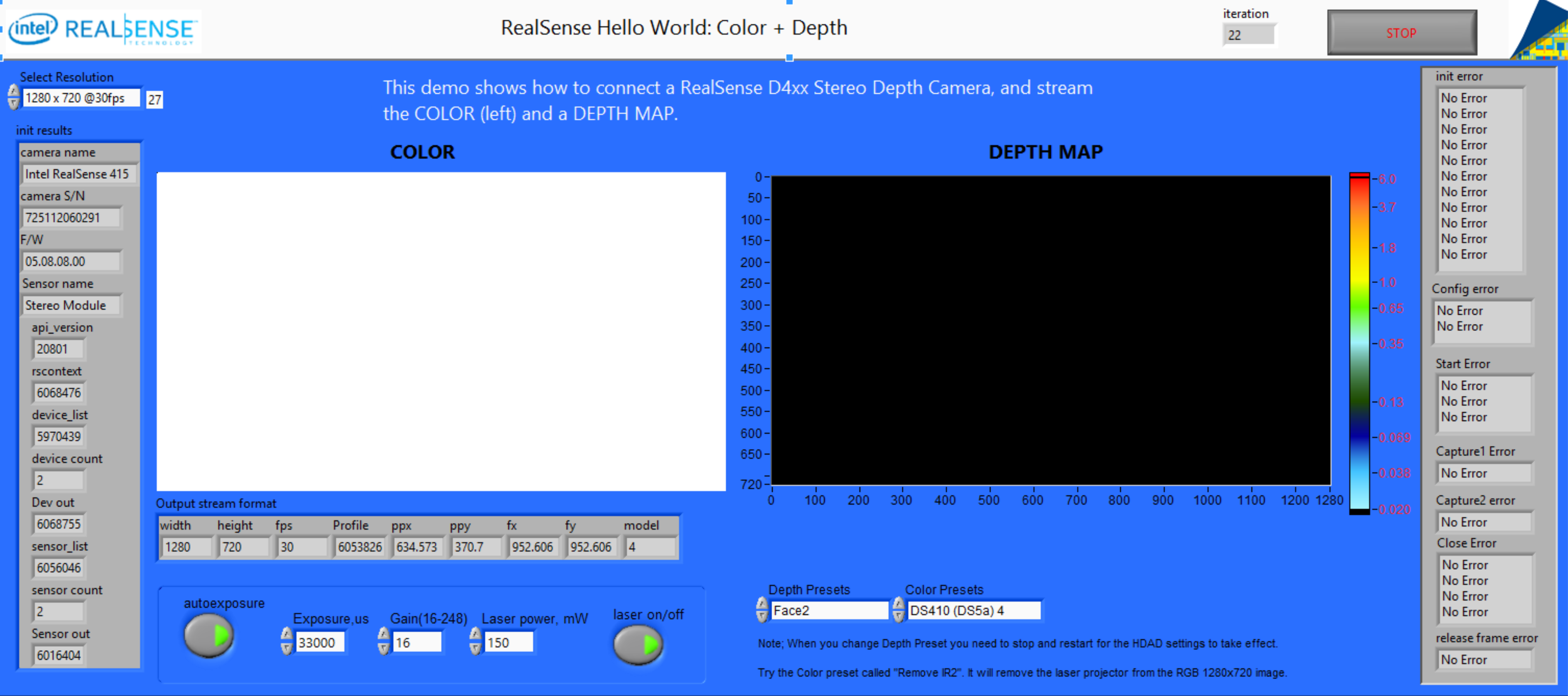
Hello World: Color + Depth
To run it, plug in a RealSense D415 or D435 depth camera, and press the run arrow. It should start streaming color and depth. The color is from the left camera of the stereo pair. There is also a different Color Camera that can be interfaced to, that has better quality images that have been processed by an ISP, but one benefit of the “Left color” is that it is matched pixel perfect to the depth and does not need any host UV-mapping and calibration.
You can stop the app and change the resolution in the pull-down menu and try different resolutions. However please note that for Stereo Depth Cameras the depth resolution (i.e. the Z-axis or ranging resolution) scales with resolution, so if you chose a smaller resolution expect not just smaller X,Y resolution, but also more error in the depth error. We do note also that the minimum range, aka MinZ also scales with resolution. So while a D415 running at 1280x720 resolution will have a minZ of about 44cm, reducing the resolution to 640x360 will reduce the minZ to 22cm.
In this app you can also turn the projector on/off. While the stereo depth cameras work great on naturally textured surfaces, objects that have only a single color (ex. A white wall) with no texture will not be resolved very well in depth range if the laser projector is not turned on.
Another important feature is the “presets”. You can change the ASIC parameters that affect depth and color by changing them through the shown drop-down menus in the lower right of the screen. For example, try “Face2” for Depth and “D410 4” for Color which will give good results for the D415 camera. We do emphasize that the color image is the left image of the stereo pair, and it sees IR light as well as visible light. This means that when you are near sunlight that generated lots of IR light, the image will perhaps be a bit purple. Also, when the projector is on, the projector pattern will be visible. We do however have an interesting trick that can remove this: When in 1280x720, try to select the Color preset called “Remove IR2”. This will not affect the depth adversely, as we are removing the pattern in the ASIC.
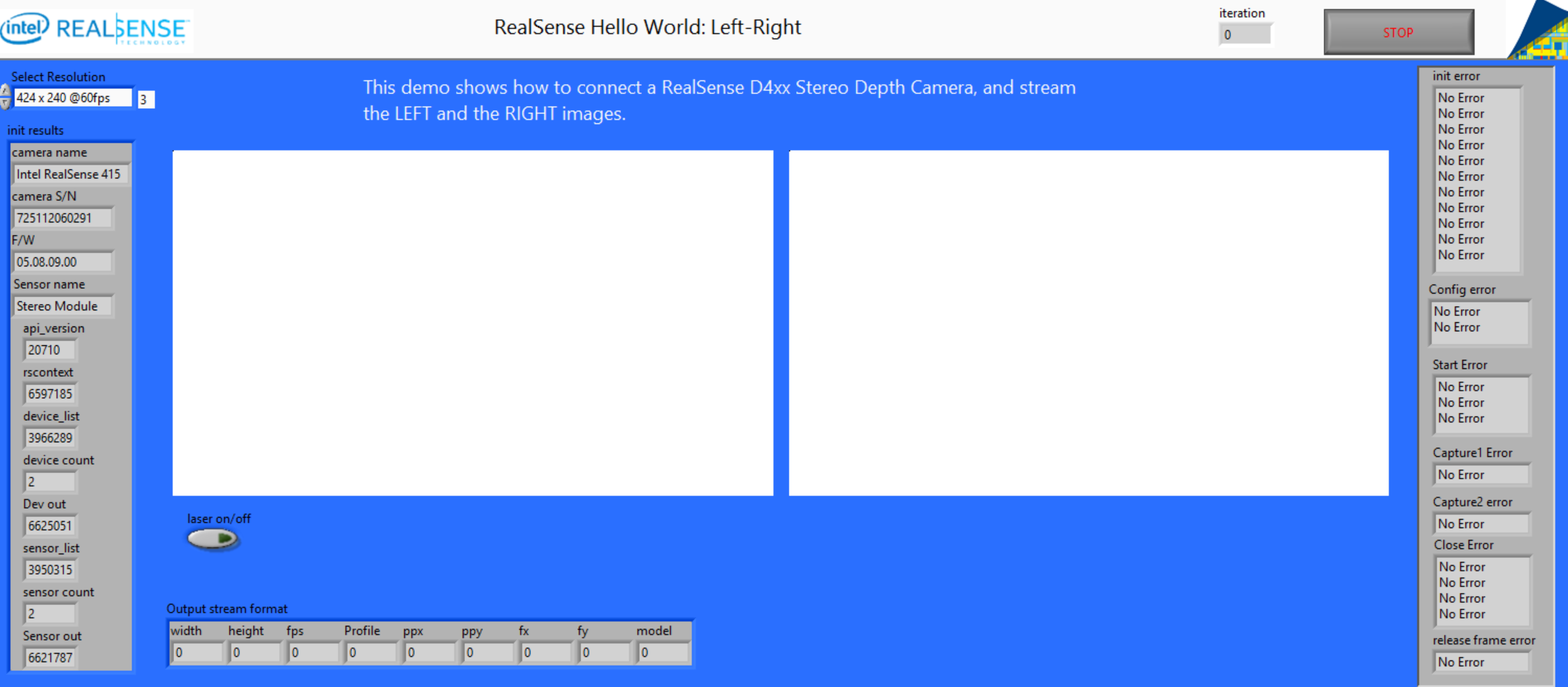
Hello World: Left-Right
You can also access directly the left and right channels of the stereo camera. We should note that only certain combinations are allowed, such as Color+Depth or Monochrome L+R. The monochrome images in this demo are 8 bit grey-scale and are after rectification by the RealSense ASIC. This is the input that will go to the stereo calculation engine inside the ASIC. It is therefore perfectly calibrated to the depth.
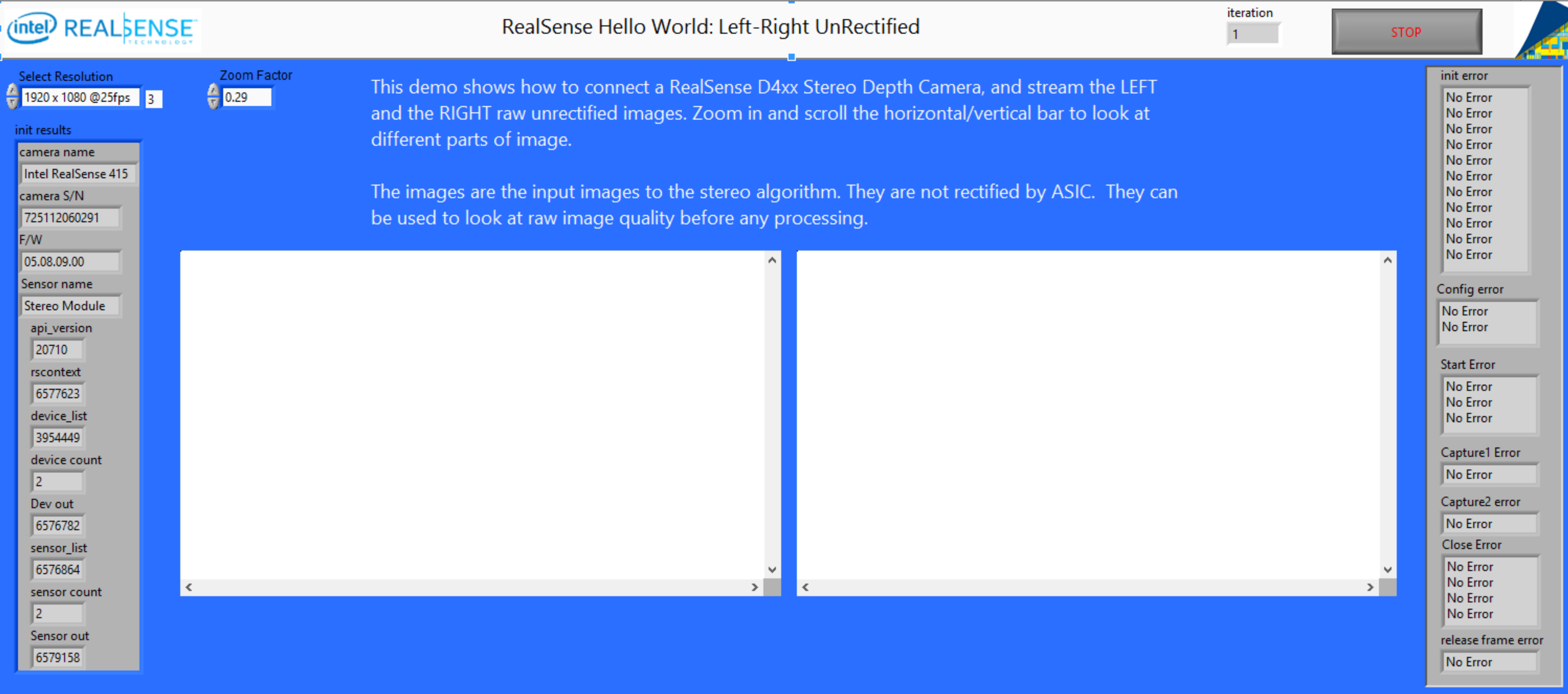
Hello World: Left-Right UnRectified
This is similar to demo 2 above, but allows you to look at the raw images that are input into the ASIC before calibration and rectification. This can be useful in for debugging if depth is bad, but more importantly it can give 2MP 16bit monochrome images
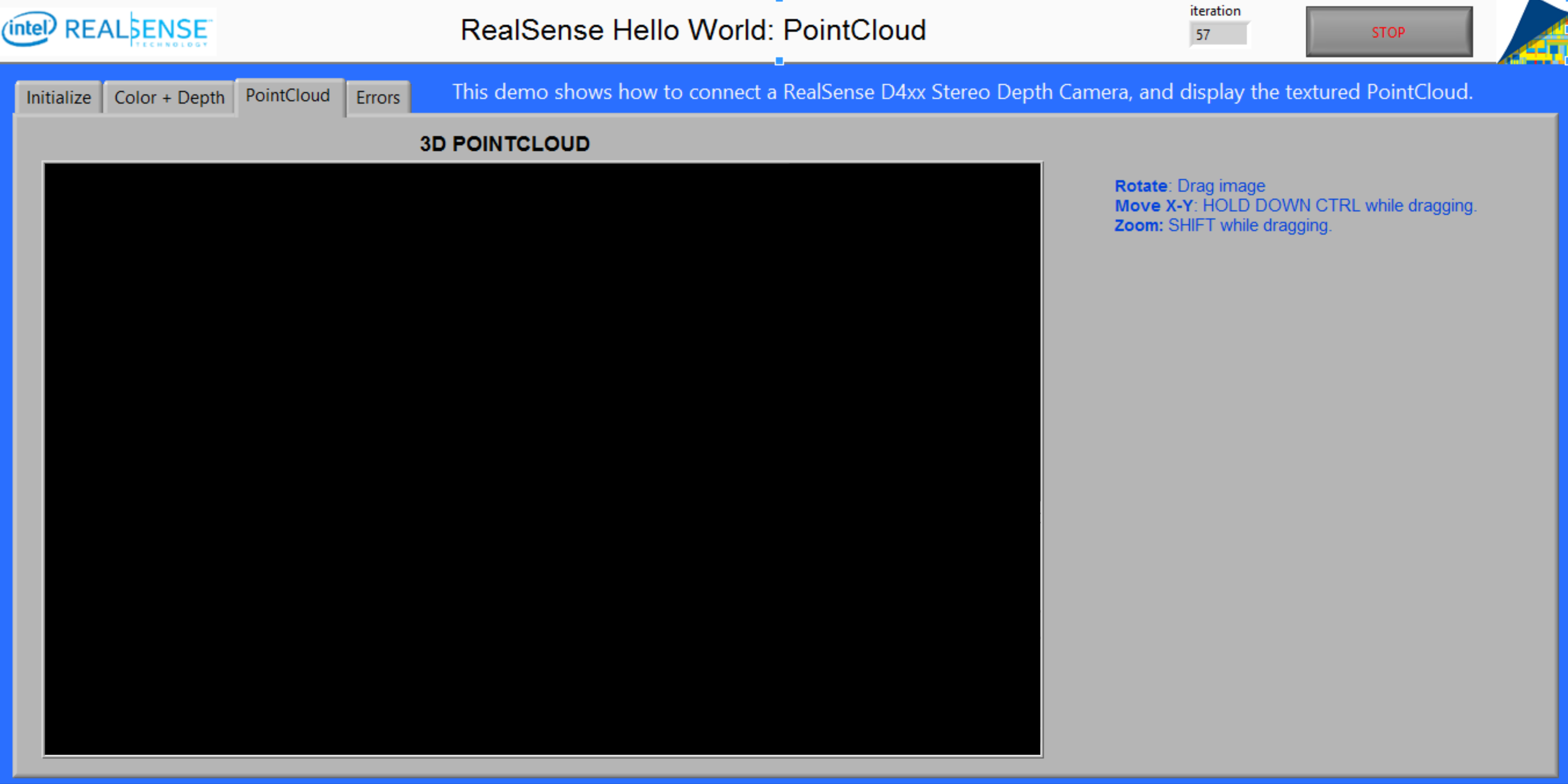
Hello World: Point Cloud
This demo builds on the Color+Depth demo, and reads the intrinsic and extrinsic parameters from the ASIC so that it can render a Point Cloud by mapping each pixel consisting of (Red, Green, Blue, Depth) to points in 3D space. Here you can rotate the 3D view of the point cloud.
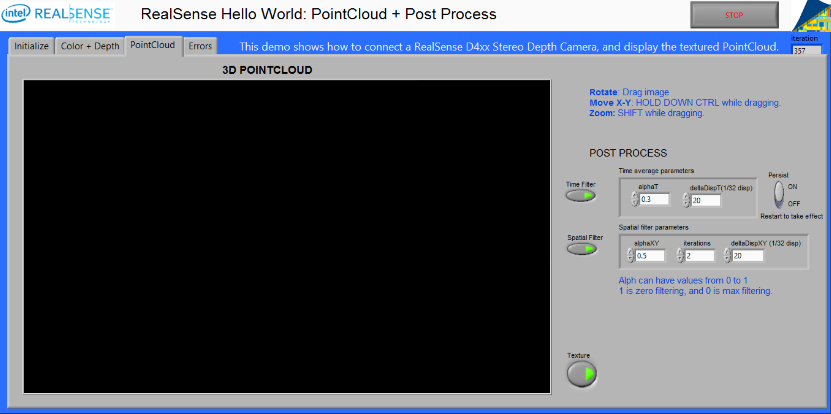
Hello World: Point Cloud Plus
This demo builds on the Point Cloud demo, by adding time stamping and also showing some simple post-processing of the Point-Cloud data to enhance it will edge-preserving temporal and spatial filters. You can select increase the filtering by setting the alpha values to near 0, and reduce the filtering by settings alpha near 1. The step size should be less than 20 for best results.
Understanding the Programming
While all the VI’s do have embedded documentation, it should in principle all be “self-explanatory”. It is however not completely straight forward and it requires some explanation about the LibRealSense (LibRS) architecture and in particular in what sequence the commands need to be executed, as well as what parameters are valid.
First we look at the hierarchy of devices, sensors, and streams. For further information about LibRS architecture, please refer to API architecture
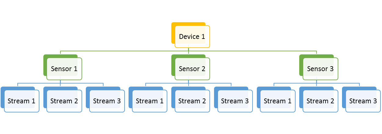
- LibRS supports being able to connect multiple DEVICES. For example, multiple RealSense Cameras can be connected at once.
- Each DEVICE can have multiple SENSORS. For example, the D415 has a Stereo Sensor and an extra RGB Sensor. Other devices may also have Fisheye sensors or IMU sensors.
- Each SENSOR can in turn have multiple STREAMS. These are, for example, the depth and color and monochrome streams. Each STREAM will be described by many different traits, such as frame rate, resolution, format, etc. Most importantly though is that each stream can be uniquely identified by a PROFILE number. A single sensor can have hundreds of streams.
When initializing and preparing to stream specific STREAMs, it is necessary to find their specific PROFILE numbers. So this means that the best way to start a RealSense Device to stream data, is to enumerate ALL device, sensors, and streams, and search for the one that has the features you are looking for, and remembering its PROFILE number. An array of these profiles numbers is input into the Configure VI, and the stream is officially started with the Start VI.
So now you are streaming data. To grab data you call the Capture VI inside a loop. This will give you a Frame pointer each time it is called. The VI will also tell you the type of frame captured, ie. What stream it belongs to. You can use the Get Frame Data to get a pointer to the payload. So if it is a “depth frame” we will treat the data as depth data (in this case 16bit data), and if it is a “color frame” we will treat it as color (in the case R, G, B), or as a Left Monochrome, Right monochrome etc.
Note that frames can arrive asynchronously. You can query their time stamp or counters to align them, or just grab the nearest frames in time.
Finally, it is VERY important that you use the Release Frame VI to release each frame when it is no longer needed, or you will very quickly stop streaming. Also, be sure to CLOSE everything properly, or you will have problems streaming the next time, and LabVIEW may crash.
Note: If you are looking for a different way to modify DLL file location, please refer to #1947 and consider trying github.com/ryannazaretian/librealsense/tree/master/wrappers/labview as a possible solution.
Updated over 2 years ago