Projectors for D400 Series Depth Cameras
Authors: Anders Grunnet-Jepsen, John N. Sweetser, Paul Winer, Akihiro Takagi, John Woodfill
Revision 1.0
This article is also available in PDF format.
In this white-paper we explore the questions of when, where, and why the Intel RealSense™ D4xx series of stereo-depth cameras need to use an optical projector, and more importantly, what performance benefits can be derived from optimizing the projector further or using external projectors.
1. Introduction
With Intel® RealSense™ Depth Cameras D4xx, depth is derived primarily from solving the correspondence problem between the simultaneously captured left and right video images, determining the disparity for each pixel (i.e. shift between object points in left vs right images), and calculating the depth map from disparity and triangulation1. The current generation of depth algorithm in the RealSense D4 Stereo-vision ASIC is able to pick up the slightest texture in a scene, especially in bright environments, and therefore works extremely well outdoors. However, under some conditions optically superimposing texture can be helpful, and even required. “Active” stereo vision relies on the addition of an optical projector that overlays the observed scene with a semi-random texture that facilitates finding correspondences, in particular in the case of texture-less surfaces like indoor dimly lit white walls. Figure 1 shows where these projectors are located on the D415 and D435 depth camera models.

Figure 1: Placement of IR pattern projectors for the Intel RealSense D415 and D435 depth cameras.
Furthermore, different types of projectors were used for each camera. The D415 uses two AMS Heptagon projectors, while the D435 uses an AMS Princeton Optronics projector with a wider emission angle but fewer spots (~5000). The optical patterns from both models projected onto a flat wall are shown below, as recorded by a D435.
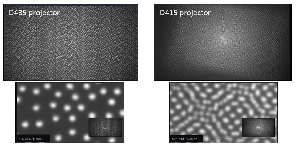
Fig. 2: IR dot pattern for the Intel RealSense D435 and D415 depth cameras. The D435 projector emits at 91x65deg, while the D415 emits at 68x43 deg.
In the current systems, these projectors have been placed between the left and right stereo imagers, and they are generally also synched to turn on only when required. However, it is important to note that this is not a strict requirement. For Active Stereo Depth systems, no a priori knowledge of the projection pattern is needed and there is no requirement of strict stability over time of these patterns. Also, it does not matter if other cameras point at the same scene with their projectors. To a first order, all additional projectors actually improve the overall performance by adding more light and more texture. We emphasize this property here, because it is in stark contrast to “structured light” or “coded light” depth sensors that many are familiar with (ex: The Microsoft Kinect, RealSense F200 and SR305, Orbbec Astra, or Apple iPhone X) where there are strong requirements on pattern stability across time and temperature that ultimately lead to increased cost and make them more susceptible to external interference.
2. What makes the ideal projector?
The question of what makes a good projector for the Intel RealSense Depth Camera D4xx series comes up repeatedly from users who want to eke out the best system performance, or who want to build their own systems. We therefore start the analysis from a clean slate below, and look at what would constitute an ideal projector.
An ideal projector for active stereo vision would be one that:
- Projects spots in the IR spectrum - so as not to be visible by humans.
- Is small and optically efficient – so as to reduce power consumption and make product integration easy.
- Has a fairly dense semi-random pattern – ideally between 20K and 300K points for a 2MP imaging system.
- Has high contrast – so that spots can be observed even in a bright room.
- Is dynamic – where spots move around, so that any residual pattern-to-depth dependence of the stereo algorithm can be averaged out
- Has little or no laser speckle – which acts to create different views from left and right imagers, and can deteriorate the depth performance by >30%.
- Is eye safe – with zero chance of causing any eye injury.
- Has programmable dot density – so that dot patterns can increase or decrease in density and dot count, depending on usage or need. This is useful when changing resolution of imaging system where density should be matched to resolution of system.
- Has an ability to redistribute power - It is very useful to have the ability to change optical range, by putting all power in fewer dots, for example.
- Is grey scale – so that more complex patterns can be created that can have high fill factor while still showing unique pattern.
- Has a texture which is scale-invariant – meaning that it will show structure at many different ranges. This is mainly relevant if the projector is not mounted together with the stereo imaging system, or if multiple independent cameras look at the same object, but may be located at different distances away.
- Is cost effective and widely available – to make mass production feasible.
- Has wide Depth-of-field – meaning the pattern is well defined and not blurry, across the whole depth operating range.
- Have long lifetime – so it does not need replacing very often.
Unfortunately, this ideal projector is not currently available, although constant improvements are being made in the industry.
3. Defining Performance
So where do we start? First, we need to define a set of key performance metrics that will allow us to compare projector performance. We recommend focusing on two initially that relate directly to the depth camera performance, although other factors are important:
-
**Range**, as determined by fill ratio - we define the fill ratio as the percentage of depth pixels that have a non-zero value, normally taken by looking at a flat wall so that occlusions do not contribute negatively to this parameter. Generally, fill ratio will decrease with increased distance for a system that relies on projected texture and thus can be a limiting factor in defining the maximum operating range. - The Depth Noise – usually defined as the RMS error of a plane fit when measuring a flat wall. This can be normalized into a range-independent number called the subpixel resolution or precision.
We can refer to these as “Can I see it?” and “How well do I see it?”, respectively.
While the fill ratio is self-explanatory, the subpixel resolution is obtained as:

Subpixel resolution equation
Where the depth RMS error is the noise of a localized plane fit (generally the “bumps” or in some cases “egg carton effect”), focal length is the depth sensor’s focal length normalized to depth pixels, baseline is the distance between the left and right imagers, Distance is the range to the wall, HFOV is the horizontal field-of-view of the stereo imager, and Xres is the horizontal resolution at which the measurement is done, for example 1280 or 848. The HFOV, Baseline, and Focal Lengths can be obtained by querying for the camera intrinsics and extrinsics. For the D415 with HFOV~65deg and baseline is ~55mm, while for the D435, the HFOV~90deg and baseline~50mm. Below we show an example of a point cloud measured on a wall where the right image has about 3x better subpixel RMS error.

Fig. 3: The depth noise observed by looking at the point cloud of a white wall. The right image has about 3x better RMS error than on the left as a result of a projector pattern with ~3x higher density texture.
For the D4 ASIC the minimum quantization step is 0.032 pixels. For well calibrated cameras, the D415 and D435 projectors normally lead to a subpixel error of about 0.07 - 0.11. For a completely well textured target (with projector off, and uniform illumination) we can measure subpixel error as low as 0.03 - 0.05. We will look later in this document at how we achieve this performance, and even exceed it, with a projector. Note that for projector comparison we generally recommend measuring the RMS error near a central 10-20% region of interest, to avoid issues that may arrive from lens distortion, calibration non-uniformity, and more importantly the uniformity of the actual flat target.
Moreover, care must be taken when measuring these values. For example, normally you will need to change the “Depth Units” in the advanced mode of the RealSense SDK 2.0 (aka LibRS). By default the ASIC provides 16bit depth with a depth unit set to 1000um (1mm). This means the max range will be ~65m. However, by changing the depth unit to 100, for example, it will be possible to report depth at 100um steps, up to a max range of 6.5m.
Another key performance metric is the absolute Z accuracy. But this factor is mainly determined by the camera calibration and is generally not dependent on the projector pattern and therefore is not of primary importance for evaluating projectors.
4. Increasing Range
One frequent question we encounter about projectors is “How do I increase the range?”. Since the Intel RealSense depth cameras D4xx can see several hundred meters outdoors, this is normally related to trying to see a texture-less white wall indoors at a range of >5m. There are several steps that can be taken:
- Increase the power: It is possible to increase the power of the D435 and D415 projectors by >2x, from their default 150mW value to 360mW. However, a 2x power improvement gives only a sqrt(2)=1.41x improvement in range. Figure 4 shows the dependence of range vs projector power on a white wall. It is possible to also build a custom projector with higher power as long as eye-safety is properly addressed. It is beyond the scope of this paper to talk about eye-safety, but this should be a primary concern, even when trying to strobe projectors synced to global shutters.
Increasing the power essentially increases the distance over which a specific minimum required image contrast is maintained. For a given pattern, it is this contrast that ultimately limits the performance. Ambient uniform illumination is the primary cause of decreased contrast (and thus performance) in most typical usage scenarios. An illustration of the effects of both projector power and ambient uniform illumination on fill ratio and RMS error (measured here as STD) is shown in Figure 4 below. The general trends are improved fill ratio and RMS error with increasing power and, for a specific power, degraded fill ratio and RMS error with increasing ambient lighting.
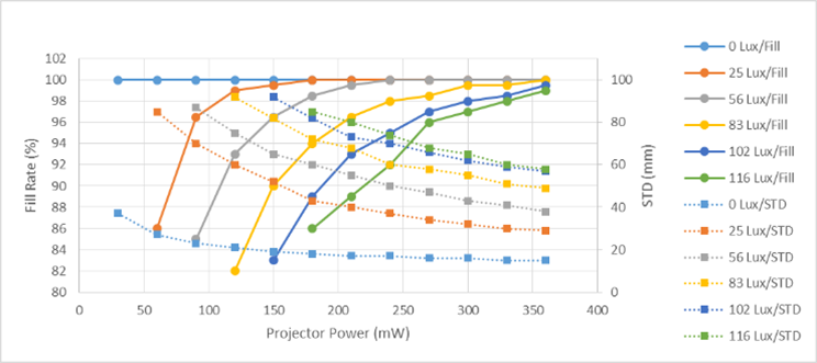
Figure 4. The fill ratio and STD on a white wall at 5m vs projector power. This is an example using a long baseline (130mm), 63 deg HFOV camera with global shutter sensors and a D415 projector, for various ambient lighting conditions.
- Use an IR bandpass filter: By attenuating visible light while passing IR light, it is possible to increase the contrast of the projector texture. Filters that transmit IR while attenuating various levels of visible light can be purchased and placed in front of the left and right stereo imagers, as long as they are optical flats that do not distort the image, which would require re-calibration. As seen in Figures 5a and 5b below, indoor white walls benefit from adding visible light attenuation, while well-textured walls benefit from having more ambient visible illumination.
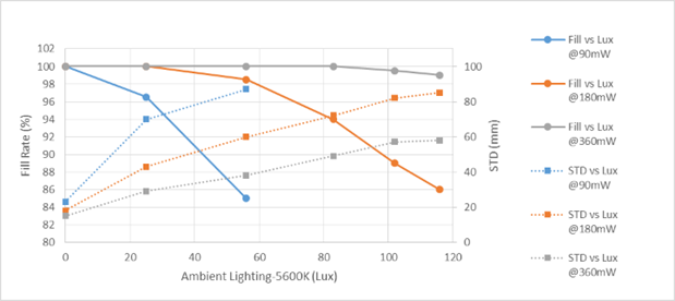
Figure 5a. The fill ratio and STD on a white wall at 5m vs ambient illumination. This is an example using a long baseline (130mm), 63 deg HFOV camera with global shutter sensors and a D415 projector. More attenuation of the room light increases contrast of the projected pattern which improves performance. This leads to an effective increase in range.
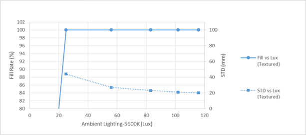
Figure 5b. The fill ratio on a TEXTURED wall at 5m vs ambient illumination. The projector is turned off. This example using the long baseline (130mm), 63 deg HFOV camera with global shutter sensors shows that the more lighting in the room, the better the STD (RMS error). It also shows that less than 25 Lux is needed to see 5 meters with a well-textured scene.
- Use Multiple Projectors: Another approach to increasing the range is to use multiple projectors. If each individual projector is rated eye-safe, more can actually be added safely, as they do not originate from the same point source. Adding more projectors can improve range and performance. More projectors means more dots (see analysis below on why that helps), and it also means that some dots overlap and increase contrast at long range. From our experiments we have observed that a doubling of the D415 projectors increases the range by about 1.2x, and not the sqrt2. This is the net effect of an increased spatial density of dots since there is little or no overlap between the two separate projector patterns.
5. The Dot Pattern
Another important and common question pertains to the dot pattern. Is there an ideal pattern? The somewhat surprising answer is that almost any pattern will work! Having spent a lot of effort on optimizing patterns, we find the key property is to simply try to make it semi-random, avoiding periodic arrangements of dots. Specific patterns tends to optimize for specific situations, like flat walls. One example of a semi-random pattern is shown in Figure 6 below.
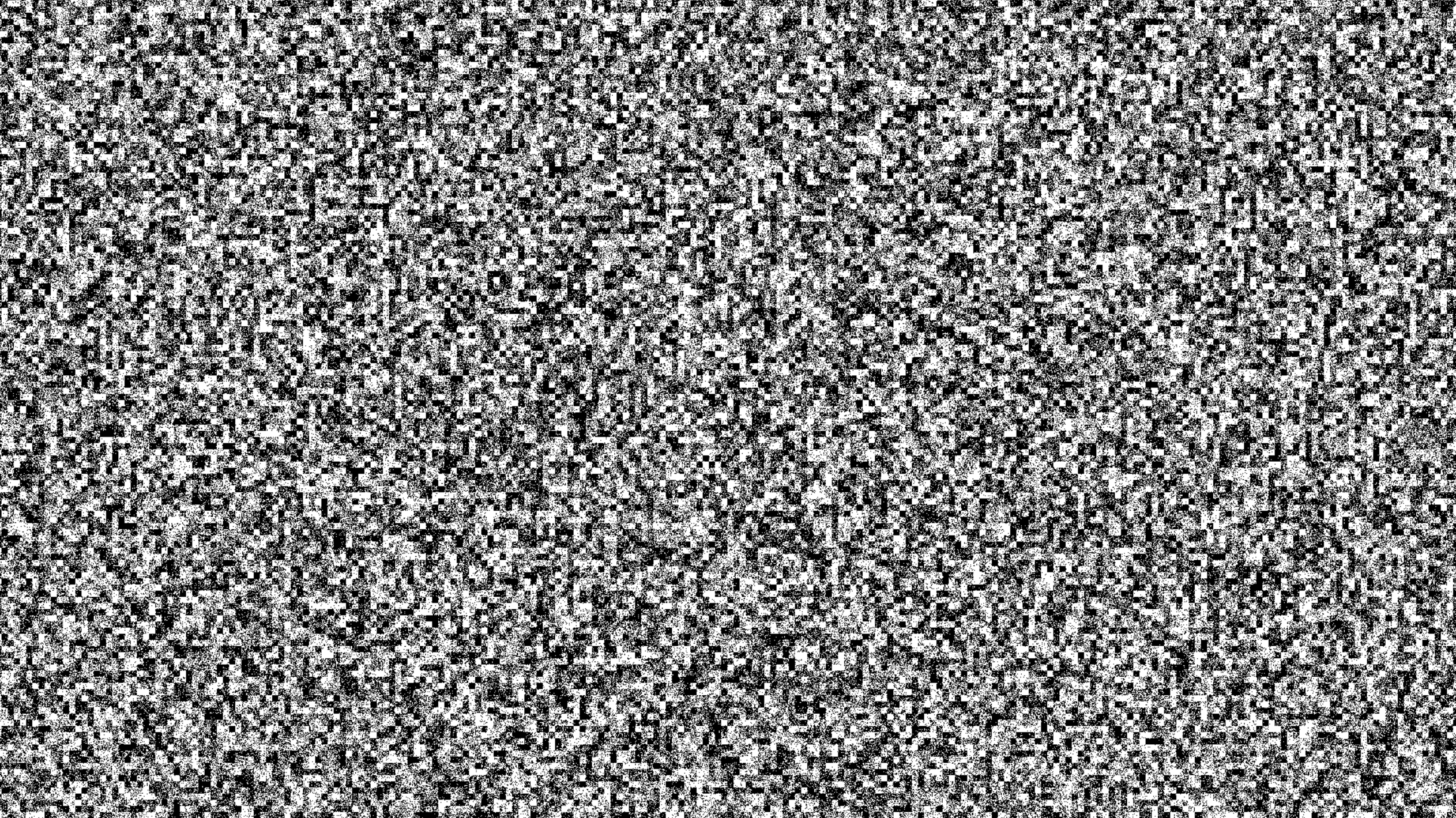
Figure 6. Example “ideal” projector pattern.
In fact, we commonly use this as a test pattern since the texture is somewhat scale invariant showing structure at both near and far distances from the target. Note that if the projector is mounted with and moves with the camera, this scale invariance is not as important because, in principle, the pattern remains mostly the same, independent of range. However, for multi-camera usages or fixed external projectors, having structure that appears at multiple scales can be important.
Using a textured pattern similar to the “ideal” one in Figure 6, the best performance possible for a particular camera design can be achieved. Fill ratios close to 100% and subpixel resolutions <0.05 are obtained over regions of the depth image that include this type of texture even at very low lighting levels or exposure times. A target of this type is useful in helping to determine optimal patterns as well as evaluating camera performance. However, in practice, very few objects in nature contain such ideal texture so it is often necessary to provide some degree of texture with a projector pattern. Relevant questions then are how close to ideal does the projected pattern need to be and what are the key characteristics of the pattern that affect performance? The full answers to these questions are beyond the scope of this paper but a few general observations can be made. As mentioned above, the key properties of the pattern are 1) effective density of dots (or more generally, the frequency of spatial variation in texture), 2) the corresponding contrast of the ‘dots’ relative to the background regions between dots, and 3) the temporal stability of the texture (i.e., dots). Properties 1 and 2 are general and apply to any pattern; 3 applies primarily to active (projected) patterns. These factors can be summarized as resolution, contrast, and temporal noise, all of which can affect the key performance metrics.
Resolution: Clearly, dot density or pattern resolution larger than the image itself is not beneficial and could even degrade performance. However, it is found that pattern resolution of only 1 to 10% of the image is sufficient to produce near ideal results. Pattern density beyond ~10% of image resolution does not result in significantly improved performance. As pattern density falls below ~1% of resolution, degradation due to sparseness of texture can begin to appear as reduced fill ratio or increased RMS error, but we have found that the fall-off is typically quite gradual such that even patterns with effective resolution less than 1% of image resolution can provide acceptable performance. The size of each dot or feature can also affect how dense the pattern needs to be to achieve a target performance.
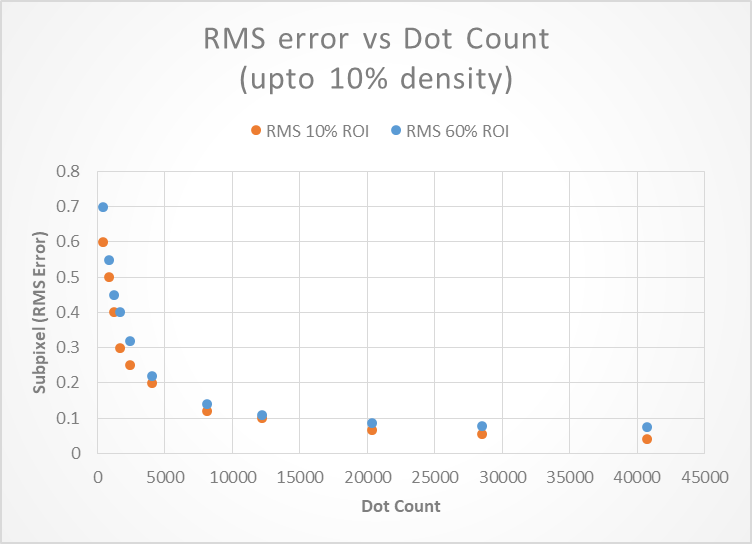
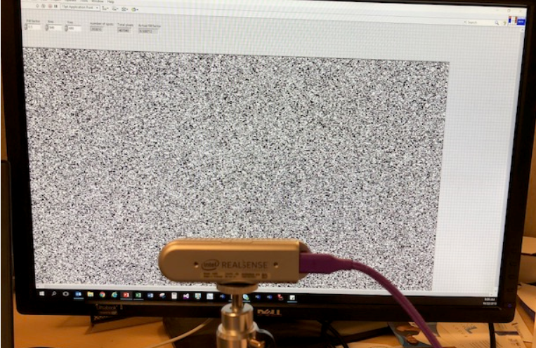
Figure 7. Measurement of Subpixel RMS error as a function of dot density on a TV screen for a D435 camera. In general >10K dots are desirable, with diminishing returns after 30K.
Contrast: Similar to resolution, texture contrast larger than the dynamic range of the sensor will not improve performance. Under ideal conditions (i.e., little or no ambient lighting and non-absorbing objects), the required contrast to achieve excellent performance is surprisingly low. The plot below shows measured RMS error vs signal-to-background ratio (which is proportional to contrast). It shows that a signal ratio > ~1.2 (equivalent to normalized contrast less than ~10%) produces near ideal RMSE values. However, since real-world conditions such as poorly reflective materials and, especially, ambient lighting will reduce the intrinsic contrast of any projector, starting with as high a contrast as possible will provide better performance in the form of better depth quality, increased range, or immunity to non-ideal ambient conditions. In practical implementation, maximizing contrast translates to concentrating as much of the available projector power into the texture dots or features and minimizing any background projector power that appears as uniform light between the dots, equivalent to excess ambient lighting.
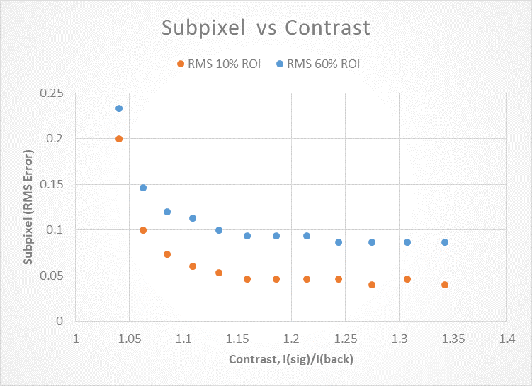
Figure 8. Measurement of Subpixel RMS error for a D435 pointed at a TV dot pattern with varying contrast. In general 15% contrast is sufficient.
Temporal Noise: The temporal noise associated with passive operation, relying on natural or intrinsic scene texture, is very low, and in most cases negligible compared with the spatial noise across the image. However, during active operation, in particular when the camera is dependent on the projector to provide valid depth, temporal noise can increase significantly and become comparable to or larger than the spatial noise. Various aspects of the projector’s optical source can contribute to the additional temporal noise but it is ultimately due to fluctuations in the spatial properties of the dots. Speckle associated with scattering of highly coherent light sources such as lasers is a primary cause of the temporal instability observed when using such projectors. Time varying intensities in the pattern can also lead to additional temporal noise. In either case, the result can be a larger RMS error, and thus lower effective depth resolution. Temporal filtering can help to recover some of this resolution (as will be shown in Section 9) but it is always better to start with lower noise when possible.
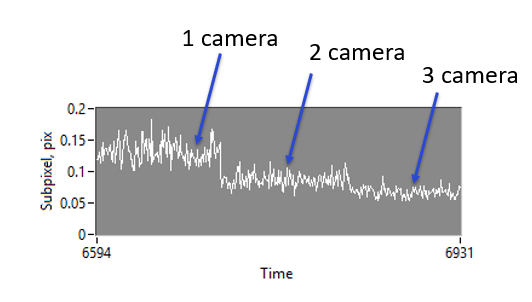
Figure 9. The Temporal noise of a single depth point for a D435 camera, as two adjacent D435 depth cameras are turned on. The average subpixel RMS noise is reduced with each additional projector, but we also see a strong reduction in temporal noise. See section 9 for more details.
6. The Consumer Front Projector
A straightforward approach to an external pattern projector is to use a standard digital video projector configured to illuminate the scene with a texture similar to the “ideal” test pattern in Figure 5. In applications where space and power are not constraints, a visible pattern is acceptable, and the usage does not require a portable or integrated projector, such an approach will work well. However, many usages prefer or require the projected pattern to be invisible to humans and thus should work in the near IR. In such cases, an IR light source based projector along with a sufficiently high resolution/high contrast image source or mask would be appropriate. Ideally, the light source is IR-only and incoherent such as IR LED arrays. Alternatively, a broadband incandescent (e.g., halogen) lamp can be used, and in cases where the pattern must be invisible, a visible-block/IR-pass filter can be placed in front of the lamp. Note that in traditional consumer projectors using broadband lamps, an IR-block filter is typically used, so that would need to be removed or replaced with the IR-pass filter. The filter can be absorptive or reflective but reflective is typically preferred to minimize thermal problems.
An example of the depth quality obtainable using a conventional visible light projector is shown in Figure 10. The projected pattern is similar to the ideal texture in Figure 6. A subpixel RMS error of ~0.04, comparable to that using the ideal printed target is obtainable. Solutions of this type may be suitable for industrial applications where the scene is fixed but the cameras and/or objects may be moving around or through it. An example would be a warehouse with objects (e.g., boxes) that need to be measured or identified moving along a conveyor belt. In scenarios such as this, a visible pattern may be acceptable.

Figure 10. A conventional visible projector (Left) used to project the pattern projected (Right image) onto a white wall. The measured RMS error was about ~0.04 pixels.
7. LED Projectors
Most current projectors used for assisted stereo or structured light cameras are laser based. There are good technical reasons for using lasers as the optical source – compact size, efficiency, and ability to control and optimize important pattern properties, such as resolution and contrast. The main disadvantages to laser-based sources are cost and coherence artifacts, such as speckle. In some cases, for example long-range applications where higher power is needed, eye-safety can also be a concern. However, there are some usage scenarios where long range and/or superior performance is not required and in such cases, potentially less expensive and simpler projector designs can be used, especially for short range applications.
LEDs are a good compromise between ideal laser sources and traditional incoherent light sources, such as lamps, in terms of cost, availability, and size. The spatial resolution and contrast for an LED-based projector pattern are lower than what is achievable using a laser-based source, and this results in an RMS error that can be 2 - 10x worse but this may be acceptable in some applications such as gross object detection or collision avoidance. On the other hand, noise associated with speckle is virtually absent with LEDs. A challenge with designing a compact and efficient projector using LED sources is the imaging system required to produce a pattern with sufficient resolution and contrast. A standard projector design could include an LED as the light source illuminating a mask that contains the texture pattern which is then projected into the scene with lenses. A simplified projector eliminates the patterned mask and uses the inherent spatial variation of the LED structure to provide the scene texture. In this case, the projection system may include a lens array that produces multiple repeated images (i.e., a mosaic). Additional structure in the form of masks or reticles may be included in such designs to improve the pattern contrast and resolution but the simplified design will typically result in worse performance than standard projection systems. Ultimately, the quality of the pattern produced by the projector is limited by both the imaging capabilities of the projection system (e.g., size, complexity, and quality of the lenses) and the properties of the mask (e.g., resolution, contrast, and transmission).
Below in Figure 11 we show a 3W and 10W LED-based projector. Using a high quality optical system including IR LED array, condenser lens, high resolution texture mask, and C-mount (2/3 inch) projection lens. Very good performance is achievable at 1m (<0.05 RMS error) with a more rapid fall-off with distance observed with the lower power version (e.g., 0.12 for 3W vs 0.055 for 10W at 3m). Other optical projection engines can be used.2
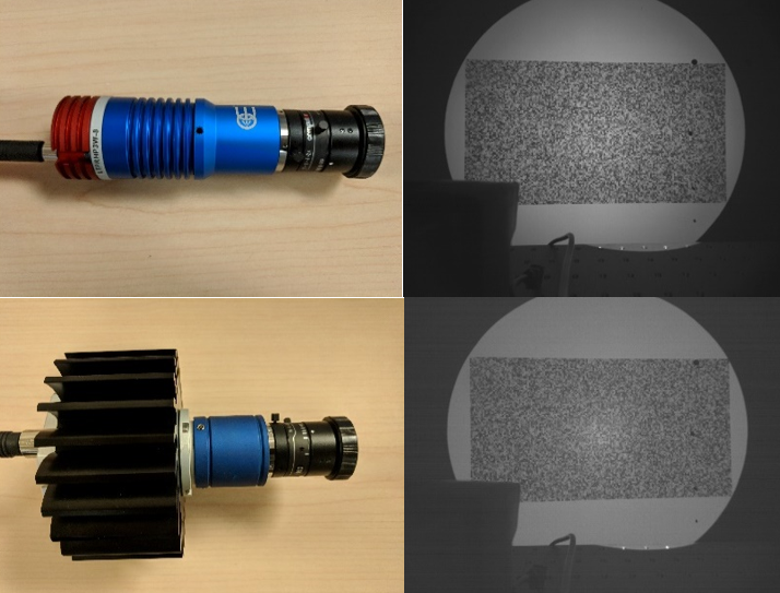
Figure 11. High power LED-based external projectors (L) and corresponding projected patterns (R). 3W model (top) and 10W (bottom).
8. Moving Patterns
Standard texture patterns are static, as they generally would be in nature. One potential advantage of an active projector is the possibility to control and vary different properties of the pattern. Advantages of such pattern control include increasing effective spot density, altering shape of features, changing illuminated field-of-view or region of interest, and reducing speckle. A simple approach to realizing some of these characteristics using an existing static pattern is to insert an optical element in front of the projector that can be controlled in some way and that can modify the spatial properties of the existing pattern.
Perhaps the simplest example of such an element is an optical wedge (e.g., a thin clear glass or plastic optic where the opposing faces are flat but form a small but well-defined angle). Light rays transmitted through the wedge will be deflected from their normal path by an angle approximately equal to ½ the wedge angle resulting in a slight displacement of the projected spots in a direction determined by the orientation of the wedge at the spot location. The deflection direction and thus the position of each projected spot can be changed by changing the orientation of the wedge, e.g., by rotating it about its Z-axis. In this way, the entire pattern will trace out the base of a cone with apex angle approximately equal to the wedge angle. Thus, the wedge angle and speed of rotation will determine the relevant properties of the modified pattern. Rotating much faster than the exposure time would result in effectively larger (or blurred) spots or, for sufficiently large wedge angles, “donut” shaped features in the projected pattern. Rotating slowly compared with the frame time would lead to texture that shifts slightly between frames.
A demonstration of the effect of a rotating wedge-based moving pattern is shown in Figure 12. For this test, a D415 projector was used as the texture source and an optical wedge was placed in front of the projector and then rotated at a controlled rate. The RMS error was measured for each of three different wedge angles (0.5, 1, 2 deg). It is evident from the data that relatively slow rotation rates for all wedges showed significant reduction in RMS error compared with static operation, equivalent to no wedge. This indicates that very little movement of the spots over the exposure time is required – the pattern remains predominantly overlapped with its initial position over each cycle. In general we observed a 20%-50% improvement by simply averaging frames, and a further 40-70% improvement by also spinning the wedge, for a total improvement of 1.8-3x. We note that we saw little improvement if we did not apply any frame averaging at all. Also, while this spinning wedge with averaging certainly helped the performance, it approaches but does not surpass that of the ideal passive target of Fig 6 or Figure 11.
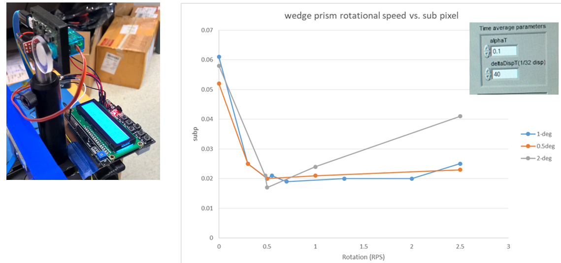
Figure 12. Rotating wedge apparatus placed in front of laser-based projector (Left), and graph of measured sub-pixel RMS error vs rotation rate for different wedge angles (Right).
More elaborate beam deflection methods and devices may also be used to produce a variety of patterns and effects. There is a wide variety of methods that can be used to convert a static projector pattern into modified pattern, dynamically changing, or even reconfigurable pattern. It is encouraging that the simplest approach shows substantial improvement in depth camera performance. It is therefore recommended to start here before moving to more complex arrangements.
9. Using Multiple Depth Cameras
We turn now to a very straightforward and simple way to improve performance – use two co-linear cameras. In the graph below we show the results of Subpixel RMS error of a D435 camera looking at a white wall at a distance of 0.9m. The simple reasoning is that if a D435 camera has ~5000 dots, then pointing two cameras at the same target will result in 10000 dots, and so on. Note that by default the D435 actually pulses its light to coincide with camera exposure. During these tests we turned that feature off to ensure that all projectors stay on all the time, as it is by default for the D415.
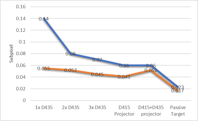
Figure 13. The subpixel RMS error of a D435 camera, when other projectors and cameras are pointed at the same target. The error is shown to decrease with increasing cameras. The blue curve is the raw data, while the red curve is after significant temporal averaging.
The left-most measurement is the subpixel RMS error measurement a single camera. The second from the left is where another D435 camera has been added, reducing the RMS error from 0.14 to 0.08. By comparison well textured passive target for this unit gives a subpixel RMS error of 0.023.
10. Laser Speckle
Laser speckle, as we mentioned before, is very detrimental to stereo vision. Laser speckle is the result of coherent interference between light reflected from slightly different points on an object.3 It is easy to experience this first hand by shining a laser pointer at a white wall (it helps to expand the beam by putting it though a lens first). Inside the resultant spot, a lot of high-spatial-frequency high-contrast noise will appear, i.e. dark and bright dots. These patterns by themselves are not the problem for stereo, as one could argue that this resembles the ideal “noisy” textured pattern, as described in Section 5. Instead, the real problem is that the pattern changes with viewing angle. This means that a left imager and right imager will NOT see the exact same pattern. This is the big problem for stereo vision which needs to match up left and right image points. This is of course also a problem for humans, and the result is that not only is there intensity noise on the image, but the speckles appears to be floating in 3D space, above the wall surface. The upshot is that a stereo camera will also see these dots as floating and it will directly lead to a larger Subpixel RMS error.
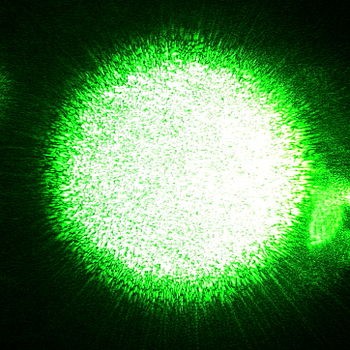
Figure 14. Laser speckle from a green laser pointer. Courtesy of ref. 3.
So why not just remove the laser speckle? It turns out that this is not trivial to do. The very nature of a laser is tied to its narrow line width and long coherence length properties, which allow it to be used to make highly optically efficient and very small projectors. There are speckle reduction techniques that have to do with trying to introduce angular, temporal, or polarization diversity into a beam. It is beyond the scope of this paper to go into these techniques. We will however mention one approach which is to simply modulate the current to the laser quickly below and above the lasing threshold, i.e. turn it on and off fast. If this is done with a little bit of optical feedback (back-reflection into the laser), it can broaden the linewidth of the laser from much less than 1nm to a more ideal 3-4nm, and dramatically reduce the Subpixel RMS noise. However, in general, if the laser is modulated, it very important that this happen very fast, ideally above 50KHz, so that temporal modulation will not be visible by the rolling shutter imagers in particular. However, the intent with this section is not to give a prescription for removing laser speckle, but instead to bring attention to this effect, and also emphasize that the way a laser is driven electronically may also be important to its operation.
11. Conclusions
We have explored some of the many considerations that go into optimizing a stereo depth solution pertaining to improving the optical projector. While the internal projectors in the Intel RealSense Depth Cameras D4xx are really quite good and possibly sufficient for 90% of use cases, they were selected with some engineering constraints on availability, size, cost and power. For example, they were not designed to be high enough power to illuminate very large rooms. It is therefore sometimes beneficial to add one or more additional external projectors. The D4xx cameras will benefit from any additional texture projected onto a scene that has no inherent texture, like a flat white wall. Ordinarily, no tuning needs to be done in the ASIC when you use an external projectors as long as it is on continuously or flickering at >50KHz, so as not to interfere with the rolling shutter or auto-exposure properties of the sensor. External projectors can also be very beneficial in fixed installations where low power consumption is not critical, like a static box measurement device. They are also good for illuminating objects that are far away, by adding illumination nearer to the object.
Regarding the specific projection pattern, we recommend somewhere between 10000 and 100,000 semi-random dots, in a pattern that is scale invariant. This means that if the separation between the projector and the depth sensor changes, then the depth sensor will still see texture across a large range of distances.
It is possible to use light in visible or near-infrared (ranging from ~400-1000nm), although we normally recommend 850nm as being a good compromise in being invisible to the human eye while still being visible to the IR sensor with about 15-40% reduction in sensitivity, depending on the sensor used.
We have also noted that when using a laser-based projectors, it is extremely important to take all means necessary to reduce the laser-speckle or it will adversely affect the depth. Non-coherent light sources will lead to best results in terms of depth noise but they cannot normally generate as high contrast pattern at long range. Even when all speckle reduction methods are employed it is not uncommon to see a passive target or LED projector give >30% better depth than a laser-based projector.
Regarding placement of the projector, as mentioned, projectors do not need to be co-located with the depth sensor, or specifically located between the two stereo sensors. It is also acceptable to move or shake the projector if desired, but it is not needed. The only last word of caution is that care should always be taken to make sure that the projectors are eye-safe.
Updated over 2 years ago
