Multi-Camera configurations with the Intel® RealSense™ LiDAR Camera L515
Authors: Ofir Mulla, Anders Grunnet-Jepsen
Revision 1.3, April 2021
This article is also available in PDF format
There are a number of important reasons for wanting to combine multiple depth sensors for simultaneous live capture of scenes. For one, arranging depth sensors in an inward-facing configuration will allow for the simultaneous capture of both the front and back of objects, so that the real-time, whole surface volumes of objects can be captured. This 3D recording can be used, for example, for Virtual- or Augmented-Reality “teleportation” and teleconferencing, or for scanning and measurement of all sides of an object. Multi-camera configurations have already been discussed for Intel RealSense stereo depth cameras (D415, D435), but in this white paper we cover the special considerations needed for the Intel RealSense LiDAR camera L515.
From a technology perspective, optical interference may occur if the L515 is arranged so that it captures scenes that consist of multiple simultaneously overlapping laser projections originating from independent L515 cameras. This means that L515 cameras that are spaced sufficiently far apart or oriented such that each camera cannot see the projected pattern from the other cameras, will NOT experience any interference, as shown in left two images of Figure 1 below. However, the right most image will lead to interference, and is the subject of this white paper.

Figure 1: Examples of configurations showing objects being scanned by multiple Intel RealSense LiDAR Camera L515s. By minimizing optical overlap, the system will be much less prone to interference, as shown by two images on left. However, the right most image shows two overlapping fields-of-view, which can lead to strong interference, unless properly mitigated.
To tackle high interference scenarios, it is recommended to enable hardware synchronization between L515 devices. This is done by implementing a master-slave configuration in order to temporally isolate the laser projections from each camera. When implementing hardware synchronization using the Intel RealSense SDK 2.0, it is can be done by enabling “Inter_Cam_Sync_Mode” which will place each L515 camera into a “slave” mode. This ensures that cameras will only trigger their laser scanning and capture when it receives a voltage-high signal on the designated hardware trigger port. It is important to note that this method of HW synchronization only applies to the depth stream. Synchronizing the RGB stream should be done using time stamps.

Figure 2: Examples of streaming simultaneously 2 Lidar in a high interference scenario where streams are not HW synchronized (middle image) showing stripe artifacts. The right-most image shows the case where interference has been eliminated (right) by using HW synchronization.
In this paper, we look at all the factors that need to be considered when connecting many Intel RealSense LiDAR Camera L515s, as well as answering the question: “How many cameras can I connect?”.
In the following analysis we examine an example of connecting four Intel® RealSense™ LiDAR Camera L515s together in the inward facing configuration. We focus our attention on capturing and displaying depth as well as the intensity and confidence maps where all cameras are connected to a single Intel Skull-Canyon NUC PC (with Intel i7-6700HQ Quad Core Processor 2.6GHz up to 3.5GHz).
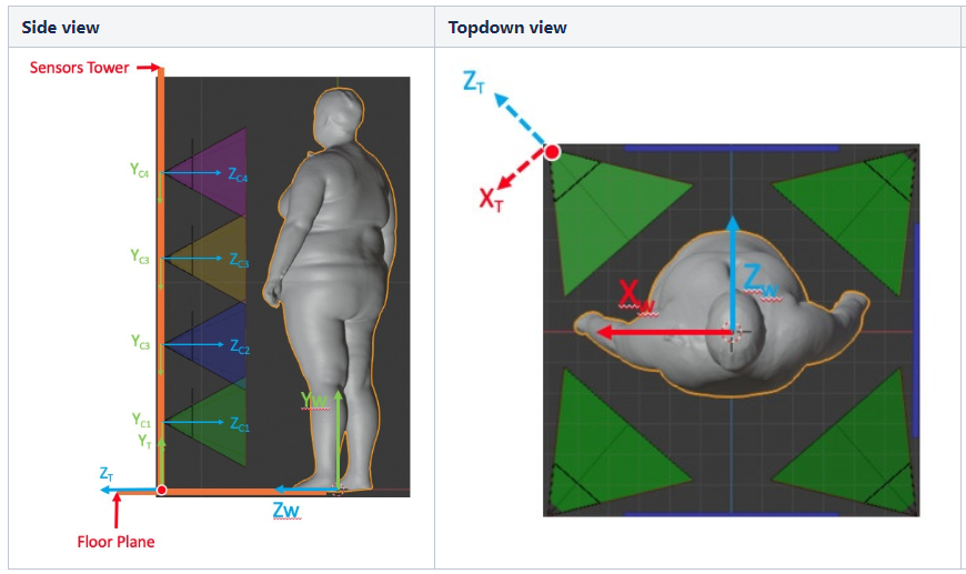
Figure 3: We will be examining how to eliminate the optical interference that may occur in examples of directly overlapping optical light fields, such as the example shown here of scanning a body using multiple parallel & collinear cameras (left), or cameras array around a person facing inwards (right).
By way of example, we will focus here on a body scanning application. In this case, we can achieve 360° scanning using only 4 cameras. However, the user can decide to add as many cameras as desired as long as a few degrees of overlap between cameras is maintained so as to get complete scans with no gaps. For example, we show on Figure 4 below a body-scanning setup that was presented at the Consumer Electronics Show in Las Vegas in 2020 which consisted of 8 cameras.
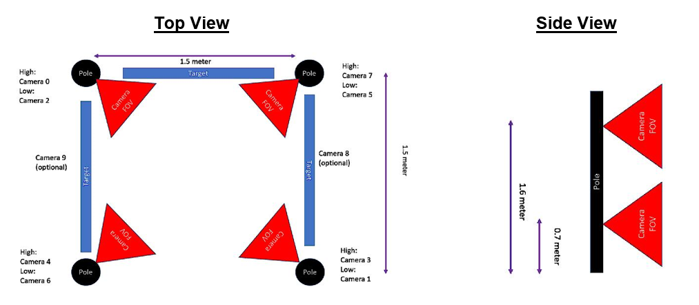
Figure 4. Body scanning camera configurations, corresponding to Figure 3, showing camera alignment in order to scan a human body. In this configuration, 8 cameras were used, as each pole had two cameras.
In addition to the L515 cameras, large optical targets were placed between the poles in order to allow for initial calibration between the cameras, as shown in Figure 5.
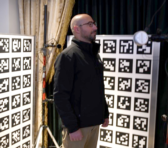
Figure 5. Flat targets containing optical fiducial markers were placed between the poles in order to facilitate alignment and extrinsic calibration of all the cameras.
In the following, we are going to go step-by-step through all the actions that needs to be taken to ensure that there is no interference when multiple cameras are used.
1. Connecting the cameras
Multiple cameras can be connected to a PC and will be able to stream independent data. Normally, the cameras operate in the “Default” mode and will stream asynchronously. However, as mentioned earlier, they can be HW synchronized so that separate cameras project light staggered in time (i.e. to reduce optical interference) and data streams do not occur simultaneously (reducing USB peak bandwidth issues). The cameras will need to be connected via sync cables, and will need to be configured in software to operate in Sync mode. The connector port can be found on the cameras as shown below, and a cable will need to be assembled. The cable should be connected to a central unit that controls the sync signals (we used Raspberry Pi4 GPIO).

Figure 6. The Intel RealSense LiDAR Camera L515, showing the location and cable connection of the HW sync port.
The Red line, shown here, is 3.3V while the black line should be connected to ground, as shown in Figure 8. The cable part numbers are detailed in the table below.
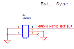
Figure 7. Schematic of the cable connection of the sync port on the L515 camera
| Type | Part # | Link |
|---|---|---|
| Board side | SM03B-SRSS-TB | https://www.digikey.com/product-detail/en/jst-sales-america-inc/SM03B-SRSS-TB-LF-SN/455-1803-1-ND/926874 |
| Cable side connector | SHR-03V-S | https://www.digikey.com/product-detail/en/jst-sales-america-inc/SHR-03V-S/455-1393-ND/759882 |
| Crimped wire | ASSHSSH28K305 | https://www.digikey.com/product-detail/en/jst-sales-america-inc/ASSHSSH28K305/455-3077-ND/6009453 |
Table 1: Part numbers for HW sync cable assembly
For HW sync, pins 1 (SYNC) and pins 2 (Ground) need to be connected as shown below. Since the L515 input is robust to ESD noise, it is possible to use up to 10m cable lengths without taking special noise filtering or shielding precautions.
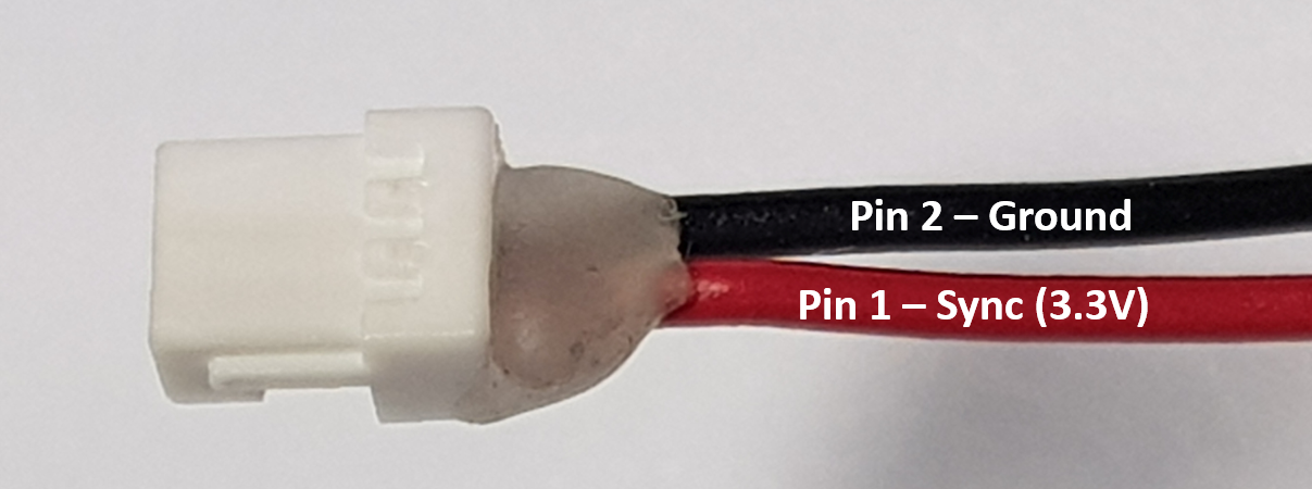
Figure 8. A close-up view of the connector and the connections. Pin 1 is the left-most pin in the image above. Pin 2 is the middle pin.
2. Multi-camera considerations:
Multiple cameras can be connected together, but exactly how many depends on several factors that will be discussed here. We start by sharing our experiences and then diving into more detail for those who want to explore pushing the limits even further. We show a table below that uses a 4-port powered USB3 hub (AmazonBasics) connected to the NUC PC. As explained before, since L515 halts the stream when it is not projecting, the only thing that needs to be taken into account is how many cameras project simultaneously. For example, it is possible to control 16 cameras as long as the number of simultaneous projections are maintained as specified in the table below. In that case the total number of cameras should not be the limiting factor. The green cells indicate that streaming has been verified successfully, while the red designates problems started occurring leading to less than the half-frame rate.

Table 2: Streaming results when using 4xL515, connected via a 4-port USB3 hub with HW sync enabled. Green designates confirmed robust streaming. This table primarily highlights how USB3 bandwidth limitations affect the choice of number of parallel USB streams.
Returning to the example shown in Figure 4, where we want to enable scanning with 8 cameras, we note that cameras on opposite sides of a person see little interference, so we opted for a HW sync configuration where we allowed opposing cameras to stream simultaneously. We used the following pseudo code:
Disable All cameras
Enable Camera 0 & Camera 1
Capture “X” frames
Disable Camera 0 & Camera 1
Enable Camera 2 & Camera 3
Capture “X” frames
Disable Camera 2 & Camera 3
Enable Camera 4 & Camera 5
Capture “X” frames
Disable Camera 4 & Camera 5
Enable Camera 6 & Camera 7
Capture “X” frames
Disable Camera 6 & Camera 7
As a result, we managed to keep interference negligible and also maintain peak bandwidth lower than HUB limitations, i.e. to 2 or less simultaneously streaming cameras at 1024x720 resolution, with depth, IR, and confidence streams at 30fps.
The following section will explain in more detail some of the factors limiting the number of cameras and data streams.
A. Bandwidth
When connecting multiple cameras to a single USB 3.0 hub, the first limitation to consider is the bandwidth limitation of the host system. The USB3.0 “SuperSpeed” interface of the L515 camera in principle supports 5Gbps. However, “accounting for the encoding overhead, the raw data throughput is 4 Gbit/s, the specification considers it reasonable to achieve 3.2 Gbit/s” . Even this may be an optimistic upper limit. Based on our understanding and research the actual sustainable throughput number is 50% below the theoretical limit.
Turning now to the Intel RealSense L515 camera, the camera can operate in two resolutions: XGA (1024x720) & VGA (640x480). For best depth lateral performance (details inspection) it is generally recommended to operate the L515 at XGA but if SNR and range are the limiting factors VGA is recommended. When operating in XGA it is recommended not to project more than 2 cameras simultaneously while for VGA up to 3 simultaneous cameras can be used, as shown in the table above.
B. Power
The USB3 specification is 900mA, or 4.5W. The power consumption of the Intel RealSense L515 Lidar camera can approach or even exceed 3W per camera. As such, a rule of thumb should be to make sure to use USB Hubs that support external power supplies, or to use individual ports on a PC that provide independent power to the USB ports. A powered HUB will normally provide 12.5W or more. Since no more than 3 cameras project simultaneously on a 4-port hub, this power is enough to drive 4 L515 cameras.
C. CPU
Attaching multiple cameras will also require processing power from the host system for reading the USB devices, streaming the high-bandwidth data, and doing some amount of real-time post processing, rendering, and application specific processing. When streaming high resolution color and depth, the processing requirements quickly add up, and will impose another important limitation that needs to be considered. We will not go into an extensive analysis of this here, except to say that care should be taken to select a computer platform that supports the intended workload.
D. Cabling and enumeration
Another perhaps mundane consideration is the cabling. Unfortunately, the quality of USB3.0 cables can vary quite a bit. For best performance, we recommend using high quality cables and using as short cables as possible - preferably less than 1m. If any bandwidth issues are observed, it can be good to replace cables or shorten them to see whether this is the cause of the errors. It is also good to confirm that the cameras are indeed connected by checking that the enumeration completed successfully on the device manager.
If it is necessary to use cables longer than 2m, we recommend using USB3 repeaters, and not just extension cables. Unfortunately, the quality of these vary tremendously. We have found that the following appears to work quite well. We have successfully strung 4 of these together.
https://www.siig.com/usb-3-0-active-repeater-cable-10m.html
E. External Trigger
For multi-camera case, an external signal generator should be used as the master trigger with all cameras set to slave mode. The trigger voltage amplitude should be @3.3V, and the first frame is triggered on the positive (rising) pulse edge.
When applying an external sync pulse, the HW SYNC input pulse width will determine how many images will be taken.

Figure 9. Timing example for external trigger
• Ton:
Pulse width = 60ms(setup) + #of frames*33ms
For example: for capturing 3 consecutive frames Ton needs to be high for 160ms
• Toff:
Pulse width should be wide enough to reduce risk for interference
There is some delay between the time the laser is turned on by the external trigger and the first frame is forwarded to the host. First, a 10ms laser warm up period is required. Then, depending on when the signal is received, the system may wait up to three frames before sending a valid frame to the host. This waiting period ensures that a high-quality frame is sent to the host.

Figure 10. Enable received at least 10ms before end of frame.

Figure 11. Enable received at the last ~6ms of the frame.
Note: Driver strength recommendation is 8mA-16mA.
For the 8-camera body-scanning demo, the following capture waveform was generated (leading to the results shown in Section 3). A single scan completes in 640ms.
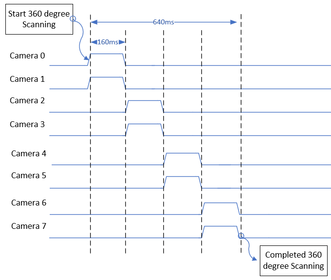
Figure 12. Example timing diagram of trigger signals sent to the 8 different L515 cameras used in the body scanning demonstration. Each camera (placed in slave mode), will only capture during signal-high. This diagram shows how pairs of cameras were turned on at a time, for 160ms captures, for a total capture time of 640ms.
3. Multi-Camera Programming:
There are two ways to program the L515 to operate in Sync mode:
• Option A: During initialization and configuration phase
o Code is a bit more complex
o No frame drops as camera always operate in interlaced mode
• Option B: During streaming
o Simpler code
o A few initial frames will suffer from interference and frame drops before HW sync becomes fully enabled
We recommend Option A, enabling hardware sync mode prior to streaming. This is described below in code block A. but we also show the code for Option B below.
A. Programming trigger configuration prior to streaming
pipeline p;
config cfg;
cfg.enable_stream(RS2_STREAM_DEPTH);
auto r = cfg.resolve(p);
r.get_device().query_sensors().front().set_option(RS2_OPTION_INTER_CAM_SYNC_MODE, 1.f);
p.start(cfg);
auto frames = p.wait_for_frames();
auto d = frames.get_depth_frame();
B. Programming triggered capture during streaming
pipeline p;
config cfg;
cfg.enable_stream(RS2_STREAM_DEPTH);
auto r = p.start(cfg);
r.get_device().query_sensors().front().set_option(RS2_OPTION_INTER_CAM_SYNC_MODE, 1.f);
auto frames = p.wait_for_frames();
auto d = frames.get_depth_frame();
C. Point-cloud stitching
Once depth maps and color images have been captured from each frame, the next step is to calculate their 3D point-clouds and to align them. There are methods known in the art for doing this. In our example, we found it sufficient to simply rotate the point-cloud data from each camera using a 3D affine transform that would rotate and shift the point-clouds and form one large composite point cloud. This code shows basic point-cloud stitching with ROS and is not limited to specific cameras, like the L515 or D400.
https://github.com/IntelRealSense/realsense-ros/wiki/showcase-of-using-3-cameras-in-2-machines
Finally we turn to the payoff – the 3D scan. Figure 11 shows the results obtained with the 8-camera capture rig.
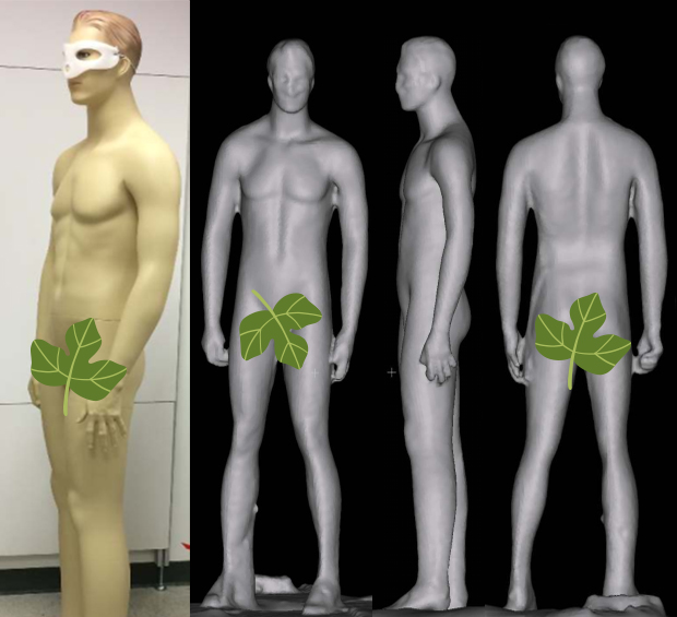
Figure 13. Example of resultant 3D reconstruction derived from combining the point-clouds from the 8x L515 cameras
4. Summary
We have explored here a number of the most important considerations for capturing 3D depth using multiple Intel® RealSense™ LiDAR Camera L515s simultaneously, and have highlighted the limitations associated with USB3 bandwidth, power consumption, CPU power, latency, and physical cabling.
Appendix
The following section will show a simple code how to generate a sequence of GPIO sync between the cameras over Raspberry Pi 4
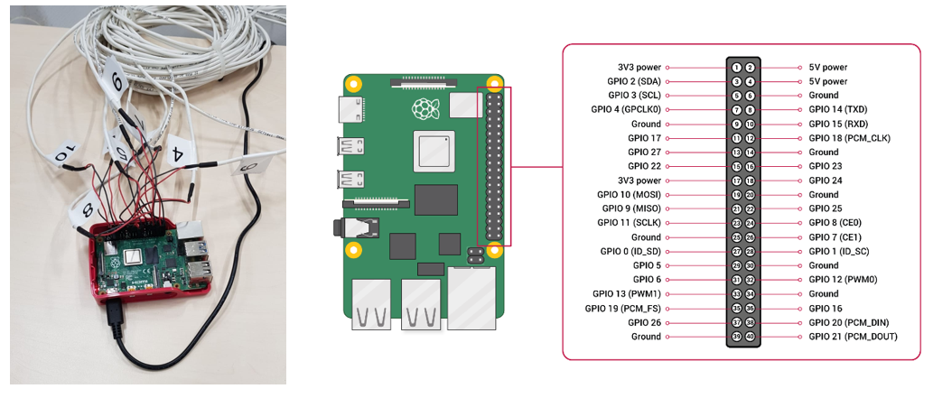
Example of using Raspberry Pi 4 to generate sync signals
#!/usr/bin/python3
import RPi.GPIO as GPIO
import time
Camera0 = 7
Camera1 = 23
Camera2 = 37
Camera3 = 12
Camera4 = 18
Camera5 = 22
Camera6 = 32
Camera7 = 36
GPIO.setmode(GPIO.BOARD)
GPIO.setup(Camera0, GPIO.OUT)
GPIO.setup(Camera1, GPIO.OUT)
GPIO.setup(Camera2, GPIO.OUT)
GPIO.setup(Camera3, GPIO.OUT)
GPIO.setup(Camera4, GPIO.OUT)
GPIO.setup(Camera5, GPIO.OUT)
GPIO.setup(Camera6, GPIO.OUT)
GPIO.setup(Camera7, GPIO.OUT)

GPIO.output(Camera0, GPIO.HIGH)
GPIO.output(Camera1, GPIO.HIGH)
time.sleep(0.16)
GPIO.output(Camera0, GPIO.LOW)
GPIO.output(Camera1, GPIO. LOW)
GPIO.output(Camera2, GPIO.HIGH)
GPIO.output(Camera3, GPIO.HIGH)
time.sleep(0.16)
GPIO.output(Camera2, GPIO.LOW)
GPIO.output(Camera3, GPIO. LOW)
GPIO.output(Camera4, GPIO.HIGH)
GPIO.output(Camera5, GPIO.HIGH)
time.sleep(0.16)
GPIO.output(Camera4, GPIO.LOW)
GPIO.output(Camera5, GPIO.LOW)
GPIO.output(Camera6, GPIO.HIGH)
GPIO.output(Camera7, GPIO.HIGH)
time.sleep(0.16)
GPIO.output(Camera6, GPIO.LOW)
GPIO.output(Camera7, GPIO LOW)

GPIO.cleanup()
Updated over 2 years ago
