OpenCV
These examples demonstrate how to integrate Intel RealSense cameras with opencv in domain of computer-vision.
They complement the C++ SDK examples
Intel RealSense examples have been designed and tested with OpenCV 3.4,
Working with latest OpenCV 4 requires minor code changes
Installation Guidelines
Please refer to installation guide according to OS:
List of Examples
Sample code source code is available on GitHub
1. Minimal OpenCV application for visualizing depth data
imShow example is a "hello-world" code snippet for Intel RealSense cameras integration with OpenCV. The sample will open an OpenCV UI window and render colorized depth stream to it.
The following code snippet is used to create cv::Mat from rs2::frame:
// Query frame size (width and height)
const int w = depth.as<rs2::video_frame>().get_width();
const int h = depth.as<rs2::video_frame>().get_height();

// Create OpenCV matrix of size (w,h) from the colorized depth data
Mat image(Size(w, h), CV_8UC3, (void*)depth.get_data(), Mat::AUTO_STEP);
2. Simple background removal using the GrabCut algorithm
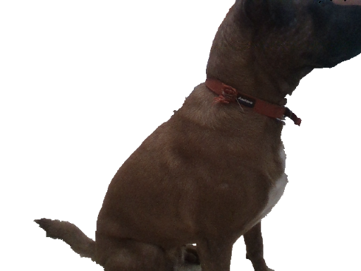
GrabCuts example demonstrates how to enhance existing 2D algorithms with 3D data: GrabCut algorithm is commonly used for interactive, user-assisted foreground extraction.
In this demo we replace the user input with initial guess based on depth data.
Get Aligned Color & Depth
We start by getting a pair of spatially and temporally synchronized frames:
frameset data = pipe.wait_for_frames();
// Make sure the frameset is spatialy aligned
// (each pixel in depth image corresponds to the same pixel in the color image)
frameset aligned_set = align_to.process(data);
frame depth = aligned_set.get_depth_frame();
auto color_mat = frame_to_mat(aligned_set.get_color_frame());
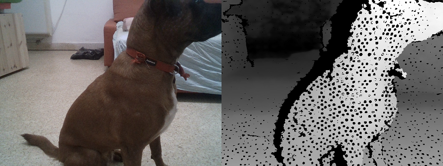
Left: Color frame, Right: Raw depth frame aligned to Color
Generate Near / Far Mask
We continue to generate pixel regions that would estimate near and far objects. We use basic morphological transformations to improve the quality of the two masks:
// Generate "near" mask image:
auto near = frame_to_mat(bw_depth);
cvtColor(near, near, CV_BGR2GRAY);
// Take just values within range [180-255]
// These will roughly correspond to near objects due to histogram equalization
create_mask_from_depth(near, 180, THRESH_BINARY);

// Generate "far" mask image:
auto far = frame_to_mat(bw_depth);
cvtColor(far, far, CV_BGR2GRAY);
// Note: 0 value does not indicate pixel near the camera, and requires special attention:
far.setTo(255, far == 0);
create_mask_from_depth(far, 100, THRESH_BINARY_INV);

Left: Foreground Guess in Green, Right: Background Guess in Red
Invoke cv::GrabCut Algorithm
The two masks are combined into a single guess:
// GrabCut algorithm needs a mask with every pixel marked as either:
// BGD, FGB, PR_BGD, PR_FGB
Mat mask;
mask.create(near.size(), CV_8UC1);
mask.setTo(Scalar::all(GC_BGD)); // Set "background" as default guess
mask.setTo(GC_PR_BGD, far == 0); // Relax this to "probably background" for pixels outside "far" region
mask.setTo(GC_FGD, near == 255); // Set pixels within the "near" region to "foreground"
We run the algorithm:
Mat bgModel, fgModel;
cv::grabCut(color_mat, mask, Rect(), bgModel, fgModel, 1, cv::GC_INIT_WITH_MASK);
And generate the resulting image:
// Extract foreground pixels based on refined mask from the algorithm
cv::Mat3b foreground = cv::Mat3b::zeros(color_mat.rows, color_mat.cols);
color_mat.copyTo(foreground, (mask == cv::GC_FGD) | (mask == cv::GC_PR_FGD));
cv::imshow(window_name, foreground);
3. Intel RealSense camera used for real-time object-detection
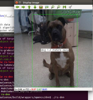
DNN example shows how to use Intel RealSense cameras with existing Deep Neural Network algorithms. The demo is derived from MobileNet Single-Shot Detector example provided with opencv. We modify it to work with Intel RealSense cameras and take advantage of depth data (in a very basic way).
The demo will load existing Caffe model (see another tutorial here) and use it to classify objects within the RGB image. Once object is detected, the demo will calculate approximate distance to the object using the depth data:
Implementation Details
Unlike the other samples, this demo requires access to the exact depth values. We generate a matrix of floating point values (in meters) using the following helper function:
auto depth_mat = depth_frame_to_meters(pipe, depth_frame);
4. Depth Filtering for Collision Avoidance
Depth Filter sample shows advanced depth-map processing techniques, developed by Daniel Pohl and Markus Achtelik for collision avoidance in outdoor drones with D400-series cameras.
The code follows closely "Depth Map Improvements for Stereo-based
Depth Cameras on Drones" paper.
Problem Statement
The problem of collision avoidance prioritizes having reliable depth over high fill-rates.
In stereo-based systems unreliable readings can occur due to several optical and algorithmic effects, including repetative geometry and moire pattern during rectification.
There are several best-known methods for removing such invalid values of depth:
- When possible, increasing IR projector will introduce sufficient amount of noise into the image and help the algorithm correctly resolve problematic cases.
- In addition to 1, blocking out the visible light using an optical filter to leave out only the projector pattern will remove false near-by depth values.
- D400 series of cameras include a set of on-chip parameters controlling depth invalidation. Loading custom "High-Confidence" preset will help the ASIC discard ambiguous pixels.
- Finally, software post-processing can be applied to keep only the high confidence depth values.
High Confidence Preset
The follow code snippet can be used to load custom preset to the device prior to streaming:
rs2::pipeline pipe;

rs2::config cfg;
cfg.enable_stream(RS2_STREAM_DEPTH, 848, 480);
cfg.enable_stream(RS2_STREAM_INFRARED, 1);

std::ifstream file("./camera-settings.json");
if (file.good())
{
    std::string str((std::istreambuf_iterator<char>(file)), std::istreambuf_iterator<char>());

    auto prof = cfg.resolve(pipe);
    if (auto advanced = prof.get_device().as<rs400::advanced_mode>())
    {
        advanced.load_json(str);
    }
}
high_confidence_filter Class
high_confidence_filter ClassNext, we define high_confidence_filter class. Inheriting from rs2::filter and implementing SDK processing-block pattern makes this algorithm composable with other SDK methods, such as rs2::pointcloud and rs2::align.
In particular, high_confidence_filter is going to consume synchronized depth and infrared pair and output new synchronized pair of downsampled and filtered depth and infrared frames.
The core idea behind this algorithm is that areas with well defined features in the infrared image are more likely to have high-confidence corresponding depth. The algorithm runs simultaneously on depth and infrared images and masks out everything except edges and corners.
Downsample Step
Downsampling is a very common first step in any depth processing algorithm. The key observation is that downsampling reduces spatial (X-Y) accuracy but preserves Z-accuracy.
It is so widespread that the SDK offers built-in downsampling method in form of rs2::decimation_filter.
It's important to note that using standard OpenCV downsampling is not ideal for depth images.
In this example we show another correct way to implement depth downsampling. It is conceptually similar to rs2::decimation_filter, picking one of the non-zero depth values for every 4x4 block, but unlike rs2::decimation_filter it is picking the closest depth value instead of median value. This makes sense in context of collision avoidance, since we want to preserve the minimal distance to an object.
Naive implementation for this approach:
for (int y = 0; y < sizeYresized; y++)
        for (int x = 0; x < source.cols; x += DOWNSAMPLE_FACTOR)
        {
            uint16_t min_value = MAX_DEPTH;

            // Loop over 4x4 quad
            for (int i = 0; i < DOWNSAMPLE_FACTOR; i++)
                for (int j = 0; j < DOWNSAMPLE_FACTOR; j++)
                {
                    auto pixel = source.at<uint16_t>(y * DOWNSAMPLE_FACTOR + i, x + j);
                    // Only include non-zero pixels in min calculation
                    if (pixel) min_value = std::min(min_value, pixel);
                }

            // If no non-zero pixels were found, mark the output as zero
            if (min_value == MAX_DEPTH) min_value = 0;

            pDest->at<uint16_t>(y, x / DOWNSAMPLE_FACTOR) = min_value;
        }
Main Filter
The core filter is doing by the following sequence of operations:
filter_edges(&sub_areas[i]); // Find edges in the infrared image
filter_harris(&sub_areas[i]); // Find corners in the infrared image
// Combine the two masks together:
cv::bitwise_or(sub_areas[i].edge_mask, sub_areas[i].harris_mask, sub_areas[i].combined_mask);

// morphology: open(src, element) = dilate(erode(src,element))
cv::morphologyEx(sub_areas[i].combined_mask, sub_areas[i].combined_mask,
    cv::MORPH_OPEN, cv::getStructuringElement(cv::MORPH_ELLIPSE, cv::Size(3, 3)));
// Copy masked depth values:
sub_areas[i].decimated_depth.copyTo(sub_areas[i].output_depth, sub_areas[i].combined_mask);
All OpenCV matrices are split into parts - sub_areas[i]. This is done to help parallelize the code, this way each execution thread can run on a seperate image area.
Edge filtering is done using OpenCV Scharr operator:
cv::Scharr(area->decimated_ir, area->scharr_x, CV_16S, 1, 0);
cv::convertScaleAbs(area->scharr_x, area->abs_scharr_x);
cv::Scharr(area->decimated_ir, area->scharr_y, CV_16S, 0, 1);
cv::convertScaleAbs(area->scharr_y, area->abs_scharr_y);
cv::addWeighted(area->abs_scharr_y, 0.5, area->abs_scharr_y, 0.5, 0, area->edge_mask);
cv::threshold(area->edge_mask, area->edge_mask, 192, 255, cv::THRESH_BINARY);
Corner filtering is done using OpenCV Harris detector:
area->decimated_ir.convertTo(area->float_ir, CV_32F);
cv::cornerHarris(area->float_ir, area->corners, 2, 3, 0.04);
cv::threshold(area->corners, area->corners, 300, 255, cv::THRESH_BINARY);
area->corners.convertTo(area->harris_mask, CV_8U);|
Optimisation
To achieve lowest possible latency the code utilizes several optimisation techniques:
- Custom (min non-zero) depth downsampling takes advantage of SSE4 instruction set when available
- Image processing is split between several execution threads using OpenMP.
-DBUILD_WITH_OPENMP=TrueCMake flag needs to be enabled for this to take effect. - All temporary image buffers are allocated once in
init_matricesand reused
Here are some rough performance measurements with these optimisations in-place:
| Platform | Average Runtime |
|---|---|
| Intel® Core™ i7-3770 CPU @ 3.40GHz, x 4 | 650 usec |
| Intel® Core™ i7-4600U CPU @ 2.10GHz x 4 | 1220 usec |
| Intel® Core™ i5-4250U CPU @ 1.30GHz x 4 | 2500 usec |
| Intel® Atom™ x5-Z8350 CPU @ 1.44GHz x 4 | 10000 usec |
Intel TBB (Threading Building Blocks) is a good alternative to OpenMP and can be used with minimal code changes
SDK Integration
The method sdk_handle is responsible for converting input frames to cv::Mat objects and resulting cv::Mat objects to new rs2::frame objects. This additional layer ensures seamless interoperability between the algorithm and the SDK.
Algorithm outputs can be later used for point-cloud generation and export, stream alignment, colorized visualization, and combined with other SDK post-processing blocks.
Upon detecting new input frame type, sdk_handle will generate new SDK video stream profile with decimated resolution and updated intrinsics.
if (!_output_ir_profile || _input_ir_profile.get() != ir_frame.get_profile().get())
{
    auto p = ir_frame.get_profile().as<rs2::video_stream_profile>();
    auto intr = p.get_intrinsics() / DOWNSAMPLE_FACTOR;
    _input_ir_profile = p;
    _output_ir_profile = p.clone(p.stream_type(), p.stream_index(), p.format(),
        p.width() / DOWNSAMPLE_FACTOR, p.height() / DOWNSAMPLE_FACTOR, intr);
}
Once output image is ready, it's copied into a new rs2::frame:
auto res_ir = src.allocate_video_frame(_output_ir_profile, ir_frame, 0,
    newW, newH, ir_frame.get_bytes_per_pixel() * newW);
memcpy((void*)res_ir.get_data(), _decimated_ir.data, newW * newH);
Finally the two resulting frames (depth and infrared) are outputed together in a rs2::frameset:
std::vector<rs2::frame> fs{ res_ir, res_depth };
auto cmp = src.allocate_composite_frame(fs);
src.frame_ready(cmp);
Once wrapped as an rs2::filter the algorithm can be applied like any other SDK processing block:
rs2::frameset data = pipe.wait_for_frames();
data = data.apply_filter(filter);
5. Basic latency estimation using computer vision
The goal of the Latency Tool sample to show how we could estimate visual latency with computer vision.
This method has a lot of unknowns and should not serve substitute to proper latency testing with dedicated equipment, but can offer some insights into camera performance and provide framework for comparison between devices / configurations.
Why is Latency Important?
Visual latency (for our use-case) is defined as the time between an event and when it is observed as a frame in the application. Different types of events have different ranges of acceptable latency.
USB webcams usually provide latencies in the order of tens-hundreds of milliseconds, since the video data is expensive to transmit, decode and process.
How this sample works?
The demo relies on the idea that if you look at a clock and a video-stream of the same clock side-by-side, the clock in the video will "lag" behind the real one by exactly the visual latency:
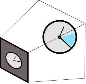
The demo will encode current clock value into binary form and render the bits to screen (circle = bit is on):

The user is asked to point the camera back at the screen to capture the pattern.
Next, we will use Hough Transform to identify sent bits in the rs2::frame we get back from the camera (marked as black squares)
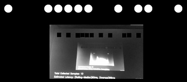
The demo filters-out bad detections using basic 2-bit Checksum.
Once it detects bits and decodes the clock value embedded in the image, the sample compares it to the clock value when rs2::frame was provided by the SDK.
Implementation Details
To make sure expensive detection logic is not preventing us from getting the frames in time, detection is being done on a seperate thread. Frames are being passed to this thread, alongside their respective clock measurements, using a concurrent queue.
We ensure that the queue will not spill, by emptying it after each successful or unsuccessful detection attempt.
Please refer to Frame Buffer Management for further information.
Controlling the Demo
Uncomment one of the following lines to select a configuration:
//cfg.enable_stream(RS2_STREAM_COLOR, RS2_FORMAT_BGR8);
//cfg.enable_stream(RS2_STREAM_COLOR, 640, 480, RS2_FORMAT_BGR8, 30);
//cfg.enable_stream(RS2_STREAM_COLOR, 1920, 1080, RS2_FORMAT_BGR8, 30);
//cfg.enable_stream(RS2_STREAM_INFRARED, 640, 480, RS2_FORMAT_Y8);
//cfg.enable_stream(RS2_STREAM_INFRARED, 1280, 720, RS2_FORMAT_Y8);
You can add more than one stream to check how multiple streams are affecting each other. The demo will however just use the first frame out of every frame-set.
This method will not work for the depth stream.
D400 will produce readable results for both RS2_STREAM_COLOR and RS2_STREAM_INFRARED. SR300 infrared stream doesn't seem to capture the content of a screen.
In addition, if you want to run this demo with a regular web-cam, use the following code instead of using the pipeline object:
context ctx;
auto dev = ctx.query_devices().front();
auto sensor = dev.query_sensors().front();
auto sps = sensor.get_stream_profiles();
stream_profile selected;
for (auto& sp : sps)
{
    if (auto vid = sp.as<video_stream_profile>())
    {
        if (vid.format() == RS2_FORMAT_BGR8 &&
            vid.width() == 640 && vid.height() == 480 &&
            vid.fps() == 30)
            selected = vid;
    }
}
sensor.open(selected);
syncer pipe;
sensor.start(pipe);
Updated over 2 years ago
