Projection, Texture-Mapping and Occlusion with Intel® RealSense™ Depth Cameras
Authors: Sergey Dorodnicov, Anders Grunnet-Jepsen, Guoping Wen
Rev 0.3
This article is also available in PDF format
1. Introduction
In order to understand its 3D environment, Intel® RealSense™ Depth Cameras combine information from multiple internal sensors. This paper offers an illustrated guide of the underlying multi-view geometry, including key concepts, algorithms and challenges. We will discuss camera intrinsic and extrinsic calibration parameters, the process of texture-mapping and stream alignment, challenges posed by occlusions and how they can be addressed efficiently using CPU and GPU computational resources.
2. Single Sensor
2.1 Camera and World Coordinates
There are two common coordinate systems used with a single camera – camera pixel coordinates and world coordinates. Each video stream is specified in pixels, with coordinates (0,0) referring to the center of the top left pixel in the image, and (w-1,h-1) to the center of the bottom right. From the perspective of the camera, the x-axis points to the right and the y-axis points down. Objects in 3D space are represented in meters, with the coordinate (0,0,0) referring to the center of the physical sensor [1]. Within this space, the positive x-axis points to the right, the positive y-axis points down, and the positive z-axis points forward.
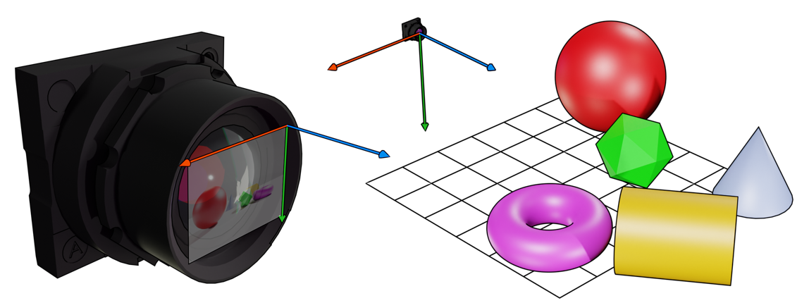
Figure 1. Camera Pixel Coordinates on the left vs World Coordinates on the right.
2.2 Projection to Camera Coordinates
The process of converting from world to camera pixel coordinates is called projection. The projection process depends on a point in world coordinates and several calibration parameters. These parameters only depend on the camera and no other components in the device, and hence referred to as intrinsic calibration parameters (rs2_intrinsics in rs_types.h):
| Parameter | Description |
|---|---|
| (w,h) | Width and height of video stream in pixels |
| P=(px,py) | Principal Point, as a pixel offset from the left edge |
| F=(fx,fy) | Focal Length in multiple of pixel size |
| Model | Lens Distortion Model |
| Coeffs=(k1,k2,k3,k4,k5) | Lens Distortion Coefficients |
Table 1. Camera Intrinsic Calibration Parameters.
Projection of point (x,y,z) is defined as:
Where D_Model: R^2→R^2 is the lens distortion function (Appendix 1)
Horizontal and Vertical Field-of-View of the camera define the limits of camera’s view frustum (Figure 2).
These parameters can be derived from Focal Length and Principle Point parameters:
Ratio of Field-of-View to Max Resolution define Pixel Density. Increasing Field-of-View allows the camera to see more of its surroundings, but it also means that each image pixel is stretched over larger physical area.
Projection point can be calculated using rs2_project_point_to_pixel method. Camera Field-of-View can be calculated using rs2_fov method. The intrinsic parameters can be obtained through get_intrinsics API:
rs2::pipeline pipe;
rs2::pipeline_profile selection = pipe.start();
auto depth_stream = selection.get_stream(RS2_STREAM_DEPTH)
 .as<rs2::video_stream_profile>();
auto resolution = std::make_pair(depth_stream.width(), depth_stream.height());
auto i = depth_stream.get_intrinsics();
auto principal_point = std::make_pair(i.ppx, i.ppy);
auto focal_length = std::make_pair(i.fx, i.fy);
rs2_distortion model = i.model;
import pyrealsense2 as rs2
pipe = rs2.pipeline()
selection = pipe.start()
depth_stream = selection.get_stream(rs2.stream.depth).as_video_stream_profile()
resolution = (depth_stream.width(), depth_stream.height())
i = depth_stream.get_intrinsics()
principal_point = (i.ppx, i.ppy)
focal_length = (i.fx, i.fy)
model = i.model
The core process of projection can be explained geometrically by building a line segment connecting 3D point to sensor origin, and checking for intersection with the camera plane:
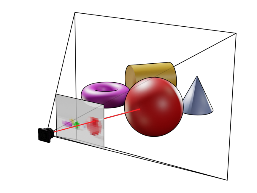
Figure 2. Projection to camera coordinates and the view frustum
Lens distortion model is applied to the result in order to account for lens non-linear geometry. Different lenses have different types of distortion and these are estimated during production-line calibration.

Figure 3. Effects of distortion. Left to right:
No distortion, Positive Radial Distortion, Extreme Distortion with a wide-FOV lens
For Intel RealSense D400 Series cameras, distortion and other related calibration parameters for unrectified frames can be queried through Calibration API. The rectified left/right and depth frames have no distortion parameters since those are processed images and hardware undistorts images during the rectification process.
On models with RGB sensor, for example, Intel RealSense D435 and D415 cameras, RGB also do not have distortion parameters since the small distortion was determined to have insignificant performance impact and excluded in the calibration process. On models with larger RGB distortion, distortion parameters will be available.
2.3 De-projection to World Coordinates
The process of projecting 3D point to pixel is not reversible. Given single pixel we can cast a ray from camera through that pixel, but it is not sufficient to reconstruct original 3D coordinates:
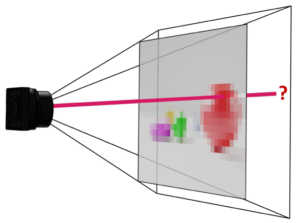
Figure 4. Ray-casting away from the camera
We can, however, complete this process if we know the depth of the pixel or its distance from the camera. These two concepts are related but are not the same. Distance of point (x,y,z) is defined as √(x^2+y^2+z^2 ) while its Depth is simply the Z-component. While these two representations are equivalent, depth maps are easier to work with and Intel RealSense Depth Cameras provide depth and not distance information.
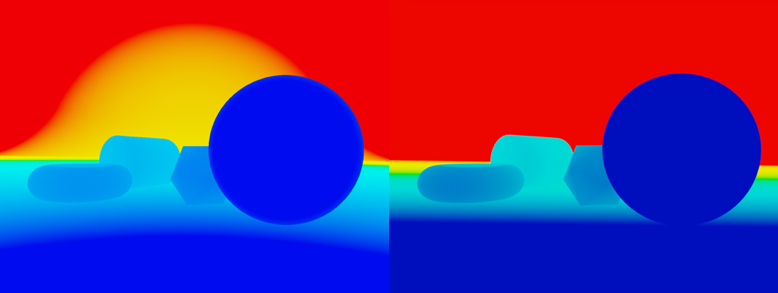
Figure 5. Distance map (left) vs Depth map (right)
Given depth pixel we can reconstruct the original point in world coordinates using the following formula:
Where UModel:R2→R2 is the undo lens distortion function.
This process will only reconstruct points visible from the camera. The resulting matrix of 3D coordinates is referred to as Point-Cloud in the SDK. Point-cloud class is designed to convert entire depth frame into point-cloud. This class is optimized differently for different platforms, but the resulting vertices should be equivalent to calling de-project on every depth pixel. Reconstructing object from 360 degrees would require multiple depth images and a process of point-cloud stitching (Reference 4).
3. Multi Sensor
3.1 Extrinsic Calibration Parameters
It is relatively rare to get both color and depth information from the same physical sensor. Having multiple sensors in a single device complicates projection process slightly. In addition to having different intrinsic calibration parameters, sensors are mounted at different positions and orientations relative to each other. Between every pair of sensors, Extrinsic calibration parameters are defined as the translation vector t and rotation matrix R connecting the two viewports
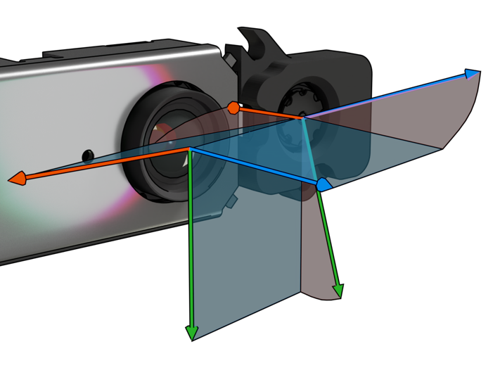
Figure 6. Translation and rotation components of extrinsic calibration between two sensors
Moving between world coordinates with respect to sensor A to world coordinates with respect to sensor B is done via matrix multiplication:
This is accomplished using rs2_transform_point_to_point method.
Every Intel RealSense Depth Camera contain multiple sensors, each with its individual viewport defined by both intrinsic and extrinsic calibration parameters (Figure 8). When using stereo depth and infrared stream with Z16 and Y8 formats respectively, D4 ASIC is generating synthetic views for the left and right infrared sensors, as if they were perfectly aligned. Querying extrinsic calibration parameters between left and right infrared streams will return R=Id and t=(b,0,0) where b is the distance between the left and the right infrared sensors, also referred to as Stereo Baseline. The L515 ASIC is doing something similar – there are no physical lenses inside the L515 camera, but rather single rectified view is being simulated by the ASIC based on responses from the LiDAR receiver.
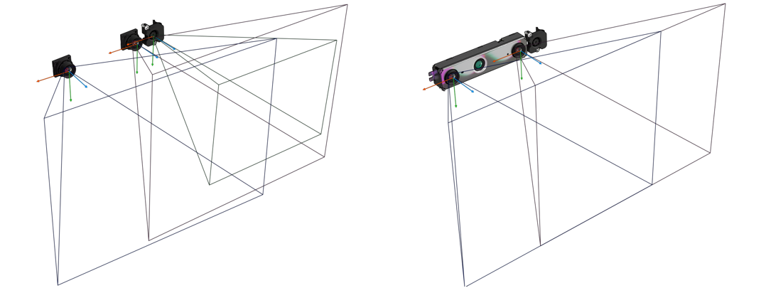
Figure 7. Unrectified (left) and rectified (right) camera views
3.2 Texture-Mapping
Using the de-projection method, we are able to generate point-cloud from depth image. The process of assigning RGB value from the color sensor to each point in the point-cloud is called Texture-Mapping.
Simply copying RGB value from same pixel in the color image will not work – the color image may be of a different resolution, may have different intrinsic calibration parameters and offset as a result of extrinsic calibration parameters between the two streams.

Figure 9. View from the color camera (left), view from the depth sensor (right), color and depth frames overlaid on top of each other (middle)
Texture-mapping process is performed using the following steps:
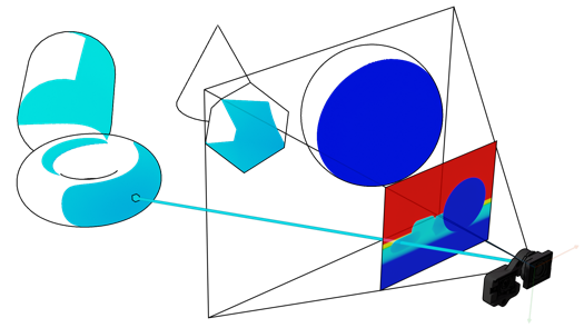
Step 1. De-project depth pixel to 3D point
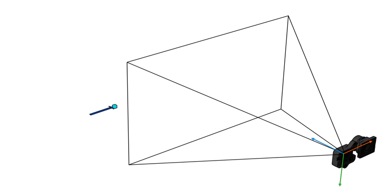
Step 2. Apply camera extrinsic matrix
(note that color sensor is becoming the new origin)
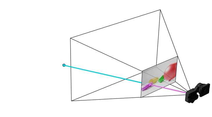
Step 3. Project point to color camera coordinates
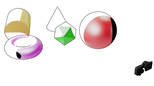
Step 4. Using camera coordinates query color value for every point (Note that not all points receive color because some are outside the field-of-view of the color sensor)
3.3 The uv-map
A notable side-product of the texture-mapping process is what’s called a uv-map. The uv-map is generated if we stop the process at step 3 (project to color) and just keep normalized pixel coordinates, instead of fetching the actual pixel value. It is the second output from SDK Pointcloud class, stored inside rs2::points alongside the vertices.
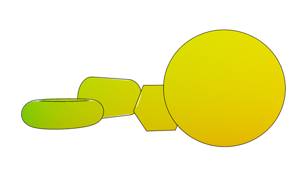
Figure 10. uv-map generated during texture mapping process
By itself, the uv-map is not very useful, but it will come handy later when dealing with alignment and occlusion.
3.4 Stream Alignment
In addition to having points in world space, it is useful to be able to generate synthetic views of how one stream would look like if it was captured from point of view of another stream.

Figure 11. Color image aligned to Depth camera coordinates (left) Depth frame aligned to Color camera coordinates (right)
To calculate Color-Aligned-to-Depth all you need is to apply the uv-Map – instead of assigning fetched RGB value to the 3D point, assign it to original pixel coordinates (i, j).
Align Color to Depth:
Calculate uv map
foreach pixel (i,j)  in depth frame:
 (k,l)=uv map(i,j)
 result(i,j)=color frame(k,l)
return result
Generating Depth-Aligned-to-Color is a bit trickier. Given pixel (i, j) inside the color image, there is no (easy) way to de-project it back to 3D space (Section 2.3). Instead, we can map all depth pixels to color coordinates. While doing so, it is important to always take the depth value closest to the camera, since more than one depth pixels may fall on the same color pixel.
Align Depth to Color:
Calculate uv map
result=zero(color frame size)
foreach pixel (i,j) in depth frame:
(k,l)=uv map(i,j)
result(k,l)=min(result(k,l),depth frame(i,j))
return result
Finally, if the color sensor has higher pixel density than the depth sensor, some color pixels will remain blank, creating holes in the output image. To combat this, instead of copying single pixel at a time, each depth pixel is extended to a 2x2 patch.
4. Occlusion Invalidation
4.1 Problem Statement
Let’s consider the following synthetic scene:

Figure 12. Setup for Occlusion demo – view from the color camera (left), depth-map (right)
If we apply Color-to-Depth Alignment or perform texture-mapping to Point-Cloud, you may notice a visible artifact in both outputs – part of the cone is projected to the cube and part of the cube was projected to the wall behind it.

Figure 13. Point-cloud with texture (left), Color aligned to Depth (right)
Given this is an artificial setup, we know that intrinsic and extrinsic calibration is perfect, so it must be something else. In context of depth-cameras this effect is referred to as occlusion.
4.2 Understanding Occlusion
Let’s pick a single green pixel on the cube and troubleshoot step by step how it came to be. We start by de-projecting depth pixel to world coordinates; we move our origin to the position of the color camera (by applying extrinsic transform) and project the resulting point back to color camera coordinates.
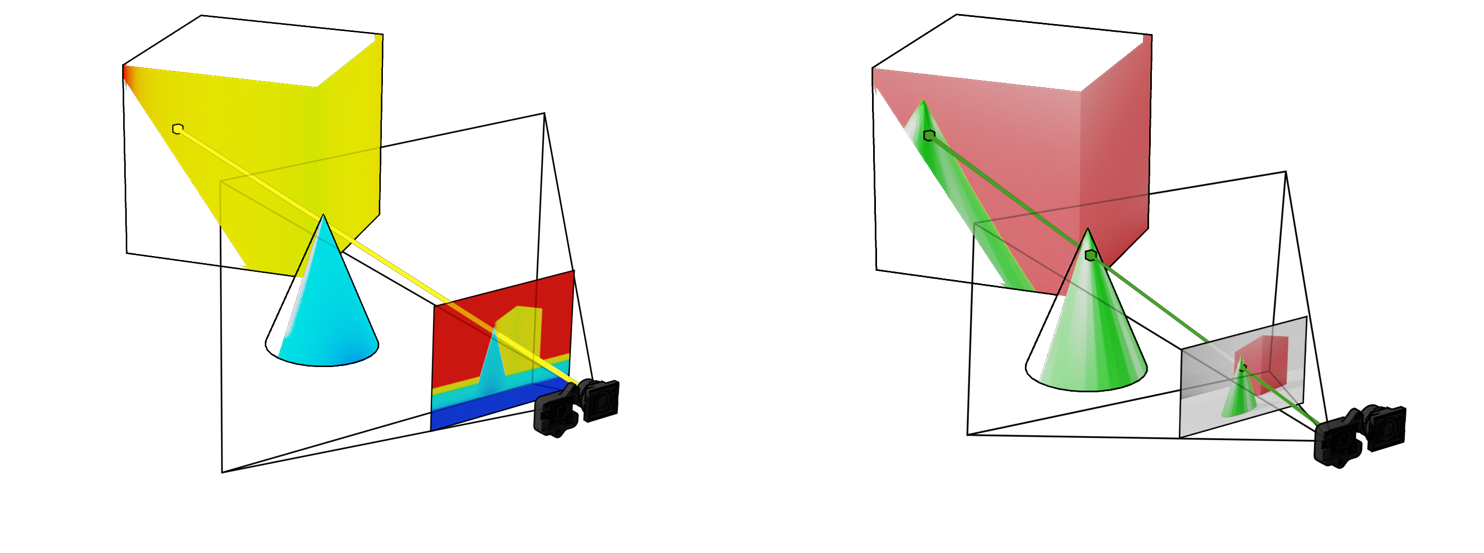
Figure 14. De-projecting pixel to point (left), re-projecting point to pixel with color as the origin (right)
When projecting back to the color camera, line segment from the 3D point to camera origin happens to intersect the scene second time, passing through the green cone. Since cone intersection was closer to the camera along this camera ray, its color was captured inside the color pixel. Another way to phrase it, is that color camera never had information about the color of this specific pixel, since it was occluded (by the cone) in color camera view.
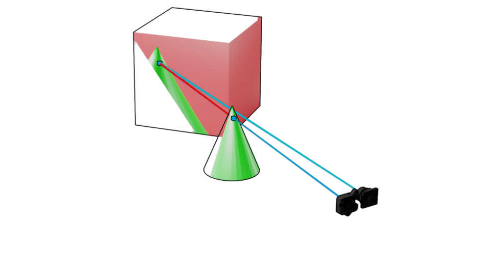
Figure 15. Occlusion recap – point on the cube is occluded from view in the color image
4.3 Occlusion Invalidation
While color information behind the cone is missing and cannot be reliably reconstructed from this data alone, it would be better to get no texture on the affected pixels instead of wrong texture.
This problem can be solved in general case by using additional projection and de-projection operations. However, for the special case of Intel RealSense Depth Cameras the SDK is using significantly more efficient algorithm. To understand it, we will need to look closer at the uv-Map. We will separate the map into u(x,y) and v(y,y) components:

Figure 16. Separated u and v components of a uv-Map
Let’s take a cross-section of u(x,y) at y=h/2 and plot the results. Within the bounds of shared field-of-view the graph is mostly monotonically increasing, except for couple of spots:
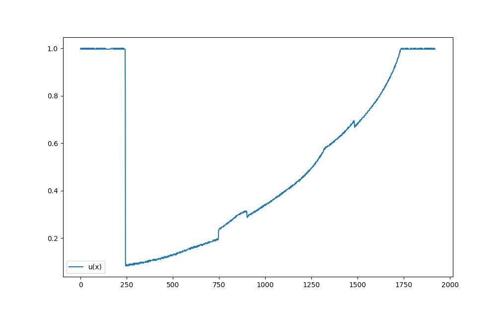
Figure 17. Cross-section of u(x,y) at y=h/2
If we overlay generated color-aligned-to-depth image on top of it, we see that occlusion area seem to begin exactly when u(x) graph decreases and disappears only when the graph recovers to its previous value.
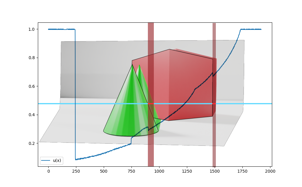
Figure 18. Relation between occlusion and uv-Map
Intuitively, this makes sense – u(x) should be monotonically increasing. If more than one value of x corresponds to a certain u, this means same color pixel would be mapped to more than one depth pixels, resulting in a similar duplication artifact.
However, would this always work? Yes and no. The reason we are seeing only horizontal occlusion with Intel RealSense D400 product-line is because in these cameras depth and color sensors are mounted horizontally next to each other. In the Intel RealSense LiDAR Camera L515, for instance, you would see vertical occlusion since its color camera is mounted on top of the lidar receiver. In this case, we would have to look at v(y) function and not u(x).
| Invalidate Occlusion | Comments |
|---|---|
| (R,t)=extrinsic between depth and color sensors | |
| if t.x>t.y: | Sensors are mounted horizontally? |
| foreach y,foreach x: | Scan depth frame horizontally |
| a=uv map(x,y).u | |
| for i=1..K: | |
| b=uv map(x-i,y).u | |
| if b>a: | |
| uv map(x,y)=0 | Invalidate output pixel |
| points(x,y)=0 | |
| else: | |
| same,swap x↔y,u↔v | Assume sensors are mounted vertically |
In theory max occlusion size can be unlimited but since we are dealing with limited resolution and range search window of 20 is sufficient.
Intel RealSense SDK 2.35+ is automatically handling occlusion invalidation as part of point-cloud calculation. We provide open-source and reasonably optimized CPU and GPU versions of the algorithm:
• CPU implementation - github.com/IntelRealSense/librealsense/blob/master/src/proc/occlusion-filter.cpp
• GPU implementation - github.com/IntelRealSense/librealsense/blob/master/src/gl/pointcloud-gl.cpp
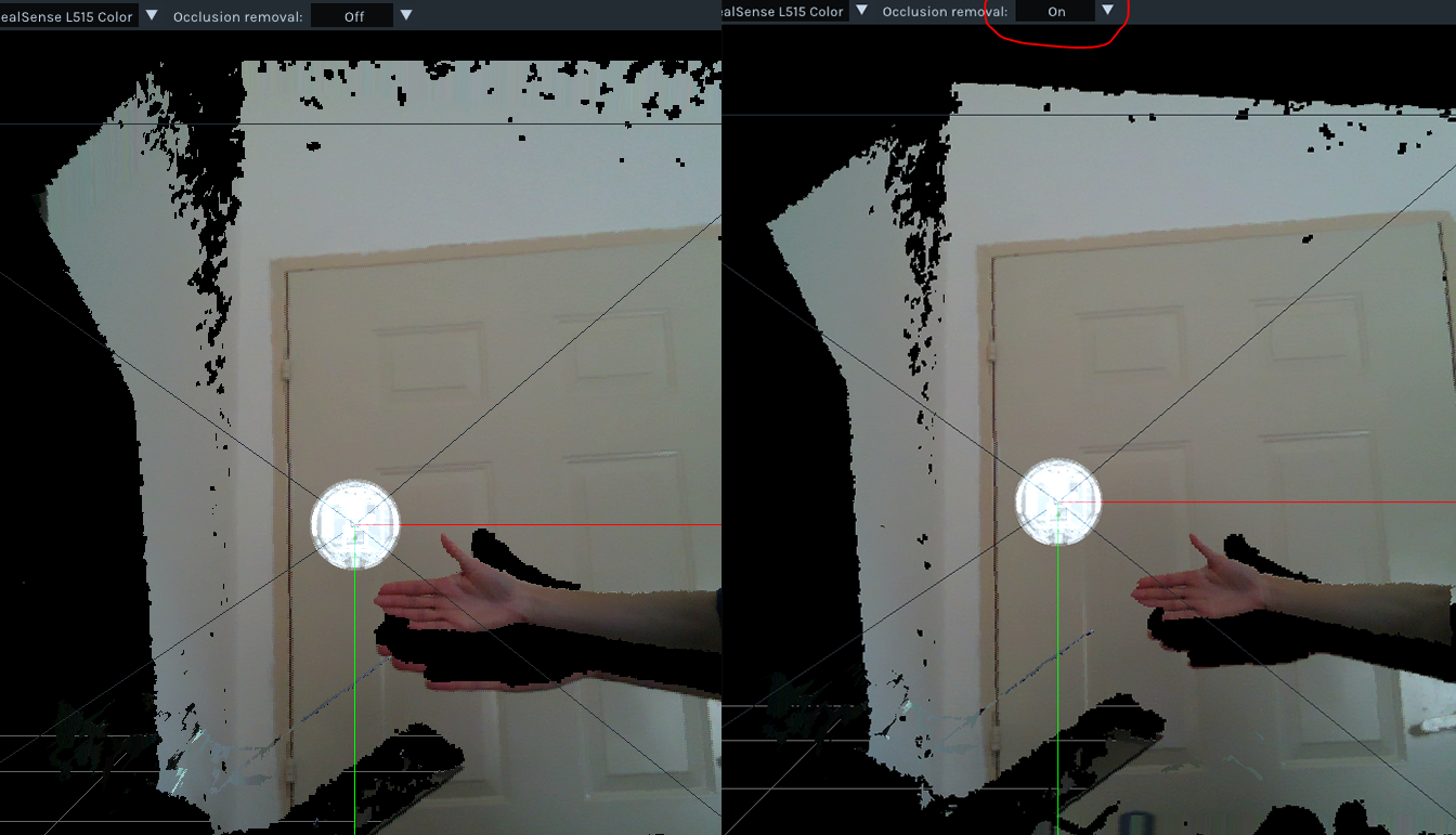
Figure 19. Occlusion Invalidation inside Intel® RealSense™ Viewer with L515 Lidar Camera
Left: Raw Point-cloud; Right: Point-cloud with occlusion invalidation enabled
5. References
- For D400 depth sensor, camera origin is not the center of physical sensor, but somewhere in between the front of the lens and the sensor. See D400 datasheet, section 4.8 Depth Start Point (Ground Zero Reference), reference 1. Similarly, L515 depth origin is inside the device, 4.5mm from the front glass. Intel® RealSense™ Product Family D400 Series Datasheet: https://dev.intelrealsense.com/docs/intel-realsense-d400-series-product-family-datasheet
- Projection in Intel RealSense SDK 2.0: https://github.com/IntelRealSense/librealsense/wiki/Projection-in-RealSense-SDK-2.0
- Camera Calibration in OpenCV: https://docs.opencv.org/2.4/modules/calib3d/doc/camera_calibration_and_3d_reconstruction.html
- Multicamera stitching with ROS: https://www.intelrealsense.com/how-to-multiple-camera-setup-with-ros/
- Calibration Tools API: https://downloadcenter.intel.com/download/29618/Intel-RealSense-D400-Series-Dynamic-Calibration-Tool
6. Appendix 1 - Distortion Models
Intel® RealSense™ Depth Cameras are currently using the following distortion models:
| Model | Distortion Formula |
|---|---|
| None | D(x,y)=(x,y) |
| Brown Conrady | r=x2+y2 f=1+k1 r+k2 r2+k5 r3 D(x,y)= (f∙x+2∙k3∙f2∙x∙y+k4(r+2x2∙f2), f∙y+2∙k3∙f2∙x∙y+k4(r+2y2∙f2)) |
| F-Theta | r=√(x2+y2 ) d=(tan-1(2r∙tan(k1/2)))/k1 D(x,y)=(d/r,d/r) |
| Kannala Brandt | r=√(x2+y2) θ=tan-1(r) d=θ∙(1+θ2(k1+θ2(k2+θ2(k3+θ2k4)))) D(x,y)=(d/r,d/r) |
Table 2. Projection Distortion Models.
Updated over 2 years ago
