Optical Filters for Intel® RealSense™ Depth Cameras D400
Rev 1.0
Authors: John Sweetser, Anders Grunnet-Jepsen
This article is also available in PDF format.
In this white paper we explore the use of various types of optical filters that can be used together with Intel® RealSense™ Depth Cameras D400 Series. Included is a discussion of different types of filters, what they are typically used for, and how they may be used to enhance both passive and active stereo cameras.
1. Introduction
With the Intel RealSense D400 series of stereo depth cameras, depth is derived primarily from solving the correspondence problem between the simultaneously captured left and right video images, determining the disparity for each pixel (i.e. shift between object points in left vs right images), and calculating the depth map from disparity and triangulation1. The current generation of depth algorithm in the Intel RealSense D4 Stereo-vision ASIC is able to detect and match pixels with local differences in image brightness or color (i.e., texture) in a scene of less than 5%. Thus, very little scene texture (natural or externally provided using a pattern projector2 ) is required in order to produce valid depth pixels.
Since good depth camera performance correlates directly with having good input images, in some special cases additional optical elements may be used to further enhance input images and depth performance. There are various types of optical elements that are candidates for depth enhancement, but for the purposes of this white paper, we refer to them generically as “optical filters."
2. What is an optical filter?
The typical notion of an optical filter is a device that is placed in the path of the light and modifies either the amplitude (i.e., intensity) or spectrum (i.e., color) of light that it transmits and/or reflects. In the case of the D400 series, these filters can be placed directly in front of either the projector or CMOS sensors3 .
The most common types of filters are those that alter the color composition of the light passing through them (e.g. colored or “stained” glass) or simply attenuate all wavelengths by the same amount (e.g. sunglasses). In this white paper, we will extend the definition to include optical elements designed to modify other characteristics of light such as its spatial properties (e.g. diffuser) or polarization state (polarizers and wave plates which modify the phase of the light). Generally speaking, temporal modification (e.g. amplitude or phase modulation over time) of light is another type of optical filter, but this topic is not discussed here.
3. Types of optical filters
A list (and brief description) of the most common optical filter types includes:
-
Broad spectrum attenuating filter – Such filters are typically called “neutral density”4, or ND filters. They are designed to simply attenuate the intensity of the incident light so that the transmitted portion has lower power. This can be done by either absorbing or reflecting a specific portion of the input light. In imaging applications, they are usually used to prevent saturation of camera images when operating near the high end of their dynamic range, e.g., in very bright conditions (full sunlight). The amount of attenuation is specified by the Optical Density, OD, on a Logarithmic scale. For example, OD1 means light is attenuated 10x. OD2 means it is attenuated 100x.
-
Spectrally selective filter – These filters have transmission that varies across the spectrum in a specified way. They are normally described by the amount of light they transmit in the desired spectral band (e.g., transmission %), the amount of light they attenuate in the blocking portion of the spectrum (i.e., the OD), and also by the steepness or width of the spectral transition or band. There is a wide variety of such filter types, some examples being:
a) Long or short pass – Designed to transmit all wavelengths either below (for short pass) or above (for long pass) a specific wavelength and attenuate or block the remaining spectrum. An “IR-cut” filter used in most consumer grade cameras is a common example of short-pass filter used to block most of the invisible IR light and transmit and improve the visible color fidelity of the image. A variant of this is a “hot mirror”, which acts like an IR-cut filter by reflecting IR light instead of absorbing it. A “cold mirror”, by contrast, is used to reflect all visible light and only transmit IR and is used in “IR photography”. Similarly, “UV filters” are used to block the UV part of the spectrum. These are often used to block UV rays which can harm live tissue and also degrade optics and sensors over time. Finally, we note that the terms high- and low-pass are also sometimes used, but they actually refer to the frequency and not wavelength, and they are the inverse. Admittedly, this can be confusing, because a high-pass (frequency) filter is actually the same as a short-pass (wavelength) filter, but in optics we usually specify responses in wavelengths, where as in RF electronics filters are usually specified according to frequency.
b) Bandpass – These filters are used to block or suppress all light outside of a prescribed wavelength range (or passband). In cases where a fairly narrow range of wavelengths is of interest and those outside this range are deleterious, a bandpass filter is used. The passband may be fairly broad (e.g., the entire visible spectrum from 380nm to 740nm), intermediate (e.g., ~50nm to cover a typical LED emission spectrum), or narrow (e.g., <5nm, to cover a typical laser linewidth).
c) Notch – This filter is essentially the inverse of a bandpass filter, where only wavelengths within the “stopband” are blocked. In general, there may be one or more distinct stopbands across the spectrum that are used to eliminate specific wavelengths typically in scientific applications such as spectroscopy and fluorescence microscopy.
- Polarizing filter – This is an optical element that transmits a specific polarization state by blocking (by absorbing or re-directing) all other states. Common optical polarization states are Linear (horizontal and vertical) and Circular (left-hand and right-hand) but can be any combination of these in elliptical states as well. “Wave plates” are a related type of optical element that can be used in combination with a polarizer6 to produce arbitrary polarization states and orientations by modifying a known input state in a controlled way. There are several different types of polarizers and they are used in a variety of applications (e.g. photography, displays, basic research), but common usages include sunglasses (using linear polarizers) and 3D glasses (using circular polarizers).
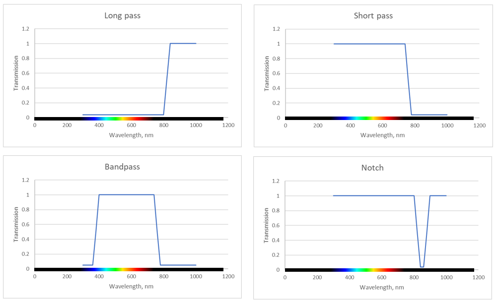
Figure 1. Wavelength selective optical filters showing examples of Long-pass, Short-pass (IR-cut), Bandpass and Notch filters. The visible range is about 380nm to 740nm.
Most of this white paper will focus on the more common attenuating types of filters defined in sections 1 and 2 which can provide the most obvious benefit for D400 series cameras. We also note that whenever we speak of adding a filter to the stereo depth camera, we do mean that filters are placed in front of both stereo pair CMOS sensors and not just one, resulting in identical filtering, or in front of the RGB sensor to enhance its color and image quality.
4. The use of optical filters
In order to motivate the discussion of the use of optical color filters with Intel RealSense depth cameras, it first makes sense to ask why one might want to do this. What are the conditions or scenarios where the addition of a filter would improve some aspect of performance? A related question is, if a filter can improve performance, why not build it into the device permanently?
4.1 When to use Neutral Density filters
A simple example of where an additional filter can improve performance is the case of extremely bright ambient lighting conditions such as bright sunlight. Under most conditions, the camera’s exposure and gain can be adjusted to accommodate a fairly large dynamic range of light levels and maintain pixel intensities below saturation. However, in cases of extreme brightness even the smallest exposure ang gain settings may not be small enough to prevent image saturation and a corresponding degradation in depth quality. In this case, simply attenuating the incident light using a filter can mitigate the problem. This is similar to putting on sunglasses while walking on the beach on a sunny day. It is also clear that just like sun-glasses, one might not want to permanently affix this filter, or the device might not function optimally in darker conditions.
For example, the D435 camera under ~100k lux illumination will saturate at the lowest exposure setting of ~10 microseconds. By placing an attenuating filter in front of each of the two stereo cameras, the intensity at the sensors can be reduced below saturation. In general, an ND filter would be used, but the optimal type of filter depends on the spectral properties of the interfering light. If, for example, a bright visible colored LED spotlight in the scene is saturating part of the image, then a visible blocking (e.g., long-pass) filter might be the better choice. On the other hand, if the bright source is predominantly IR light, an IR-blocking (IR-cut) filter is preferred. In the case of broadband ambient lighting, such as sunlight, any of these filter types could be used and the choice may be dictated by other considerations such as image quality or simply availability and cost.
An example of the use of an attenuating filter to mitigate the effects of image saturation is shown in Figure 2. It is always most instructive to look at the left stereo imager (monochrome or color image) of the Intel RealSense camera to see whether saturation is taking place, as it will show up as white untextured regions which are easily identifiable as originating from saturation (as seen in the lower part of the lower right image). If one looks only at the depth image, one may simply see areas with invalid pixels or holes (z=0). However, since holes in depth can appear for a number of different reasons other than saturation (such as occlusion, no texture, miscalibration), it is much less ambiguous to look at the monochrome image to understand the underlying cause.
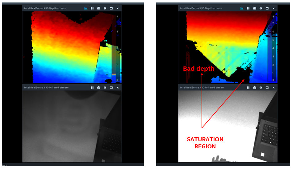
Figure 2. An example of the use of an attenuating filter to reduce image saturation and improve depth quality. A D435 camera is pointed at a concrete white outdoor ledge in bright daylight (~100k lux). On the left, a visible blocking (IR-pass) filter is placed in front of the camera and on the right the camera is used in its normal configuration. The corresponding depth maps and left camera images are shown in the top and bottom, respectively. In both cases, the camera exposure is set to its minimum value of ~10 microseconds. The additional attenuation using the filter clearly improves the depth image by reducing the image brightness in the lower portion below saturation (i.e. the saturated white image becomes grey and starts showing texture).
4.2 When to use long-pass filters
Other scenarios where the use of a filter can improve performance are where it is useful to increase the relative strength of the textured IR projector pattern compared with ambient lighting. This can be achieved by adding a long-pass filter that passes IR light from the projector but attenuates some portion of visible light, as illustrated in Figure 3. In general, since the Intel RealSense stereo cameras use both IR and Visible light to deduce depth, it is not recommended to completely block the visible. Moreover, ambient illumination generally helps stereo cameras see very far (>20m), beyond the reach of any embedded IR projector.
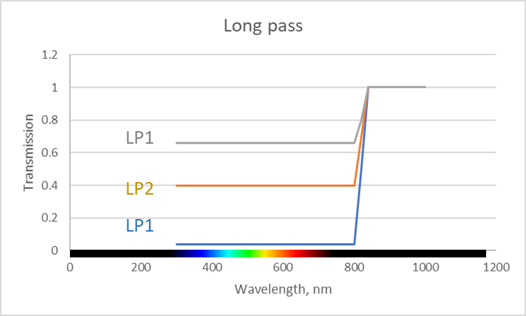
Figure 3. Showing 3 long pass filters (LP1, LP2, LP3) with different amounts of attenuation in the visible band, and full transmission in the IR. These types of filters can be used to adjust the ratio of visible light to IR light in the captured images.
The filters in Figure 3 have the effect of increasing the contrast of projector texture in the image without completely darkening the ambient image. Ambient illuminated images tend to have a lot of natural texture and in general are useful for other computer vision tasks as well, such as object recognition. Two situations where this may be beneficial are presented in the next two sub-sections.
4.2.1 Conditions with no natural texture
Long-pass filters can help in some indoor scenes. Specifically, they will help make distant white walls more visible by increasing the relative brightness of the IR projector. This works primarily if there is no other ambient IR light. By adding an IR-pass filter, the texture produced by the projector pattern will appear brighter in the image compared with the mostly uniform ambient lighting.
An example of such a scenario is illustrated below in Figures 4 and 5 using a long-baseline (130mm) prototype camera.
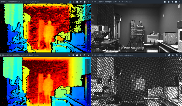
Figure 4. The effect of an IR-pass filter to increase projector contrast and enhance depth quality. The top row shows the depth (L) and left camera (R) images for a standard configuration without filter. The bottom row shows the corresponding images after filters that block most light below ~670nm and pass ~92% of light above ~750nm are placed in front of each stereo camera. All camera settings are the same and the ambient lighting is ~300 Lux fluorescent. The increase in projector contrast and improvement in depth quality, especially for distant and well-lit areas, are apparent.
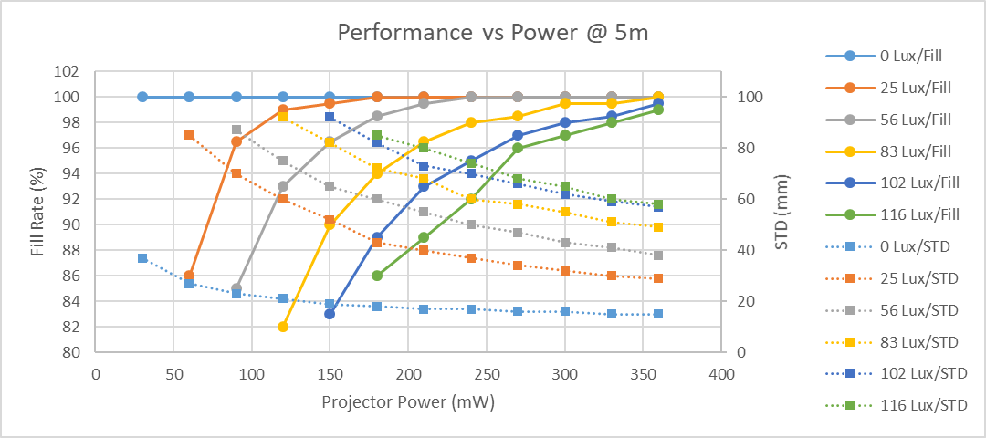
Figure 5a. The fill rate and depth noise (STD – standard deviation of plane fit) on a white wall at 5m vs projector power. This is an example using a 130 mm baseline camera with a D415 projector, for various ambient lighting conditions. As projector power increases, the depth noise (dashed lines) decreases, and the fill rate (solid lines) improves. As the ambient illumination decreases, the amount of projector power needed to reach 100% fill and low noise, decreases.
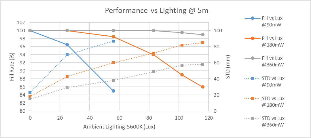
Figure 5b. Same as figure 5a but plotted as a function of ambient lighting. Less room light (e.g. room dimming or visible filter attenuation) increases the contrast of the projected pattern which improves the depth performance. This leads to an effective increase in range on texture-less walls.
We usually define two principle performance metrics for good depth: 1. fill ratio (which is ratio of valid depth points to all depth points) and 2. depth noise (which is measured on a flat wall as the standard deviation, STD, from a plane fit). These are shown as the left and right Y-axes in Figure 5b. The data shows that by improving the texture contrast one can get better performance. This means that one can either increase the projector power (different curves) or decrease ambient lighting (x-axis) using a stronger visible-attenuating filter.
Figure 5b helps to illustrate this with an example of a white wall at 5m away. Under typical indoor ambient lighting conditions of ~250 lux, a 130 mm baseline camera running with 360mW of projector power will NOT be able to see the wall very well, as fill ratio will have diminished to ~85% and STD error will have increased 4x. However, by attenuating only the visible component of light by 10x (not the IR), the fill ratio can be improved to ~100% and the STD can improve by nearly 3x.
However, care needs to be taken in finding the right balance of IR and visible light. Attenuating visible light will ALSO reduce the visibility of any naturally textured objects that may be present in the scene. Recall that the D400 cameras work extremely well at seeing natural scenes if there is a lot of visible illumination, and in some high-texture cases actually work better without an IR projector. Moreover, some objects simply do not reflect IR light, so removing all visible light is definitely not recommended.
In summary, the optimal attenuation is a balance between increasing the texture contrast provided by the projector and increasing any natural scene texture by increasing visible illumination. Taking all factors into account, some degree of visible light filtering is likely to enhance performance under indoor conditions that require seeing white walls at distances >4m.
4.2.2 Conditions with Periodic Structures or Horizontal Lines
There are certain “corner-case” scenarios where specific features in the scene can lead to artefacts in the depth image. In such cases, the addition of an IR-pass filter will help suppress the specific troublesome texture. A couple of examples of depth artefacts whose effects can be mitigated with the addition of a filter are listed below.
Repetitive structures – Features with periodicity appearing horizontally across the image (parallel to the baseline, and with a separation of less than 126 disparities) can cause problems for stereo vision because they can lead to incorrect disparity matches and thus false depth values. This aliasing effect is illustrated in Figure 6. Common natural scene examples are: slats of a picket fence, vertical blinds, and manhole grates. Stereo algorithms may match to adjacent features instead of the correct match. This can usually be mitigated by adjusting the “2nd Peak Threshold” setting in the “Advanced Parameters” settings as described in the “Tuning Depth cameras for Best performance” white paper5 . In cases where that does not work, one can project a pattern to break-up the periodicity, and an IR-enhancing filter can help.
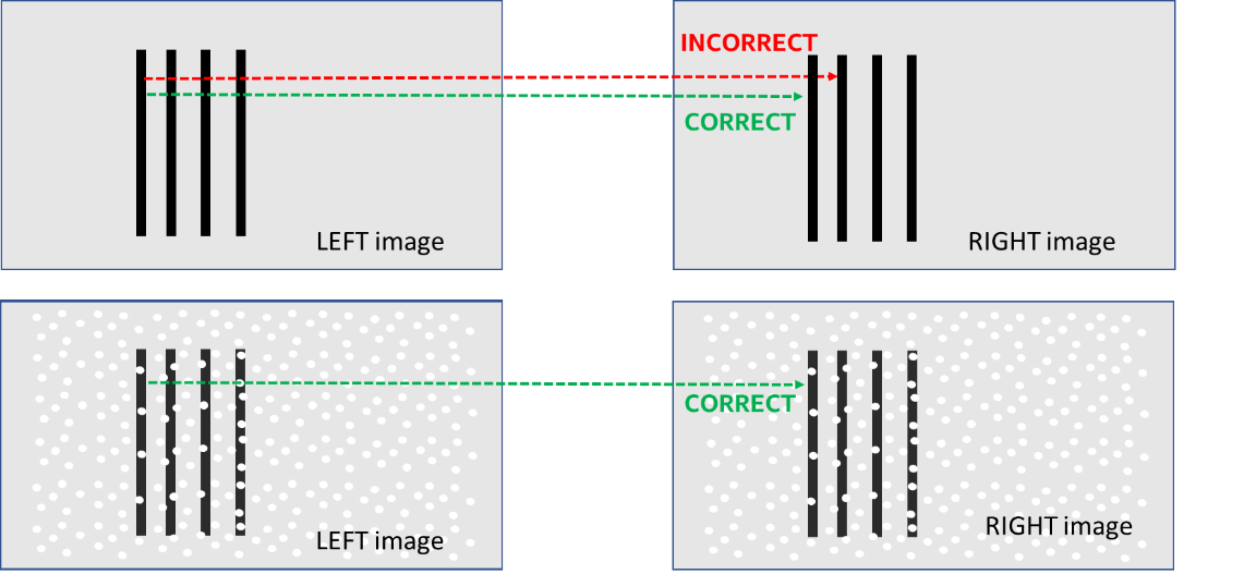
Figure 6. Example of a repetitive structure (vertical lines) that can lead to “ghost” depth, usually at a closer distance. Both depth settings and projectors can be used to mitigate this effect. In the top image, the left most line can get incorrectly matched to adjacent lines if they appear to be identical. When a textured pattern is overlaid onto the scene or its contrast enhanced with the use of an IR-pass filter (bottom), the uniqueness of the pattern makes incorrect matches much less likely.
Horizontally-aligned features – For single lines tilted slightly from parallel to the camera baseline, as shown in Figure 7, the stereo system can sometimes create “ghost depth” at a wrong distance. This effect appears when the stereo cameras are slightly miscalibrated. The reason is that even a very small vertical misalignment of the right image, can cause a large change in the disparity match. Examples of this are horizontal bars or pipes (or equivalently, vertical structures for a 90 deg rotated camera). In contrast to the repetitive structures described above, these features do not need to be repetitive or periodic in order to cause depth artefacts.
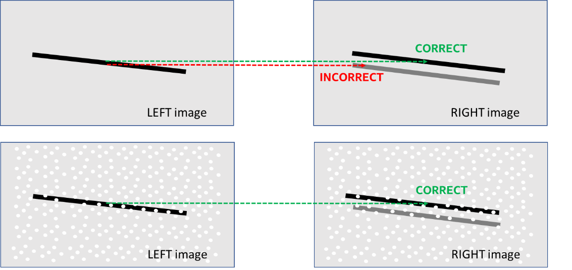
Figure 7. Example of a horizontal feature that can lead to “ghost” depth. The top image shows the effect of left-right camera vertical misalignment combined with a tilted feature. The false depth can appear either closer or father away depending on the directions of the tilt and calibration misalignment (illustrated by the displaced gray line in the right image). When a textured pattern is overlaid onto the scene or its contrast enhanced with the use of an IR-pass filter (bottom), the uniqueness of the pattern makes incorrect matches much less likely.
The first approach to mitigating this effect, is to make sure the cameras are optimally calibrated. We recommend using the new On-Chip Self-Calibration routine, described in a separate white paper.
Second, one can try to suppress the artefact-inducing horizontal lines while retaining sufficient texture to provide valid depth elsewhere. This is achieved, as described before, by increasing the relative strength of the projected pattern, even to the extreme point where only the pattern is observed and no horizontal lines. The primary limitation comes from the amount of ambient IR light that is present in the scene (such as outdoors in daylight), which can over-power the IR projector. The use of a visible-blocking filter will then only work in the near range where the projector is brighter than ambient IR light.
In the examples above we described using IR Long-pass filters. In some cases, the use of a “bandpass” filter may be better. For example, since CMOS sensors are sensitive to light of wavelength up to about 1100nm, it may be beneficial to use a ~50nm bandpass filter centered around the 850nm wavelength of the projector so that the camera is also blocked from seeing 875nm to 1100nm light. However, in practice, bandpass filters are generally much more expensive than long-pass filters, and their center wavelength shifts with incident angle. This means that the filters will be centered at 850nm for light incident near the center of the image, but for light in the edges of the image, the center of the filter can actually shift to 830nm, for example. This can cause a Field-of-view spectral variation, or “lens shading” that may want to be avoided.
4.3 When to use short-pass and notch filters
A short-pass filter can also be used in other corner cases to improve performance. The popular “IR-cut” filter, for example, is used in almost all color cameras to improve visible image quality, specifically color balance, fidelity and contrast. It achieves this by suppressing the effects of any IR light. This is especially useful in outdoor photography where the significant IR component of sunlight tends to degrade the visual quality of color images. For the D400 series depth cameras we have opted to have no built-in filters. This means we pass both IR and RGB light because we want the sensors to be able to see the IR projector, if needed. However, this means that outdoors in particular, the color images from the left stereo color camera will look very faded in color, as shown in Figure 8. For this reason, for most outdoor scenes we actually recommend using IR-cut filters. A natural scene outdoors will tend to have a lot of natural texture and bright lighting, which means that the D400 cameras provide excellent performance outdoors without need for any projector. With IR-cut filters the left image will much better reproduce nice color images. Moreover, because color from the left imager is inherently perfectly aligned with the depth map, it may even be preferable to use this instead of the dedicated separate color imager.
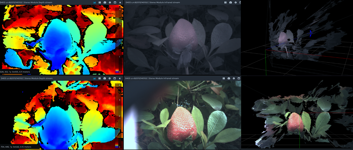
Figure 8. Example of the use of an IR-cut (short-pass) filter. A short baseline Intel RealSense camera is used to capture depth of a strawberry placed among plant leaves in a shaded outdoor environment. Shown are the depth map (Left), left RGB camera image (Middle), and 3D Point Cloud images with left camera texture overlay (Right). The top images correspond to the camera used without filter, and the bottom is the same scene but with IR-cut filters placed in front of the stereo cameras. The improvement in the RGB image and 3D texture quality is obvious. In fact, there is also slight resolution improvement in the depth image (e.g., some of the leaf veins are resolvable) due to the increased contrast.
The use of a notch filter (essentially the inverse of a bandpass filter) would be useful in scenarios where there are specific wavelength bands that may interfere with or reduce the depth quality. For example, if another device is using a laser of a specific wavelength to illuminate or scan a scene, then a notch filter can be used to block only that wavelength. This approach is sometimes used to let devices that operate at 850nm and 940nm co-exist without affecting each other at all.
4.4 When to use polarizers and waveplates
Polarizers can be used to selectively attenuate different components of light in order to enhance human vision and photography6. Here we will discuss a few examples of scenarios where the use of polarizers can enhance 3D image quality from stereo cameras.
The most common type of polarizer is a linear polarizer. Such filters are designed to pass light with a linear polarization state (aligned along its transmission axis) and block light with the perpendicular polarization state. Thus, for unpolarized or randomly polarized light, which includes most common light sources, ~50% of the incident light will be passed and ~50% will be blocked. However, it turns out that light incident on many surfaces will become partially polarized upon reflection, meaning the surface will effectively act as a polarizer. The degree of polarization as well as the fraction of light reflected depends primarily on the angle of incidence, but over a fairly broad range of angles, the reflected light will have a significant polarized component with most of the light polarized parallel to the surface. The Fresnel Equations7 describe exactly how light reflecting off a glass (or plastic or water) surface can be treated by decomposing into S- or P-polarized linear states, that reflect differently, as shown in Figure 9. Interestingly, at an incidence angle near 56 deg, called the Brewster angle8 , ALL reflected light is purely S-polarized (oriented parallel to surface).
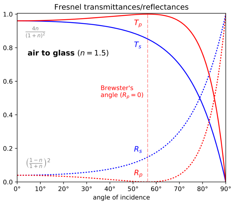
Figure 9. Reflection of light at a dielectric barrier, such as air-to-glass or air-to-water, can be described by the Fresnel equations, which decompose light into S- and P-polarization states that reflect and transmit differently. The S- refers to polarization with electric field normal to the plane of incidence, and P- refers to electric field being in the plane of incidence. At the Brewster angle, all reflected light is S-polarized, which means that a properly oriented polarizer could be used to remove all reflections.
In the picture in Figure 10, for example, a polarizer is used to reduce the glare of sunlight reflecting off a window by only passing P-polarized light7.

Figure 10. Photographs of a window with a polarizer filter rotated to two different angles. In the right picture, the polarizer was oriented to eliminate the strongly polarized reflected sunlight. Photographs reproduced from Ref. 6.
A common usage for linear polarizers is to reduce the effects of glare from specular reflections from nearly flat surfaces (e.g., the hood or windshield of a car, road surface, windows, snow, or calm body of water). By orienting the transmission axis of the polarizer appropriately with respect to the reflecting surface, a significant fraction of the reflected light can be blocked. Note that this method is effective for “Fresnel” type reflections which occur at the interface between two dielectric materials with different indexes of refraction, such as air-glass, air-water, as well as many clear coatings on surfaces (e.g., waxed or polished floors). Reflections from metallic surfaces such as standard aluminum mirrors do not experience the same polarizing effects.
So how does a polarizer help the performance of a depth camera? There are two main artefacts that can result from specular reflection: 1. Glare can lead to local saturation of portions of the image, and 2. False depth can result from objects partially reflected from the surface. Glare-induced saturation is usually associated with bright light sources such as sunlight or light bulbs. Reflection-related false depth typically occurs with textured objects reflected on shiny surfaces with little texture (ex: white tables and floors). In either case, appropriately placing linear polarizers over each of the left/right cameras can significantly suppress the corresponding artefact.
A simple, yet common, example of local saturation due to specular reflection is shown in Fig 11a. In this case, fluorescent ceiling lights reflecting off a polished tile floor show up as image saturation and missing depth pixels (i.e., a hole) in the depth image of a D435.

Figure 11a. Example of how bright ceiling lights can reflect off shiny floors and cause local image saturation and poor depth, leading to a hole in the floor, as shown on the right.
The same scene can be improved by adding inexpensive film polarizers aligned with vertical transmission axis placed over each camera as shown in Fig 11b.
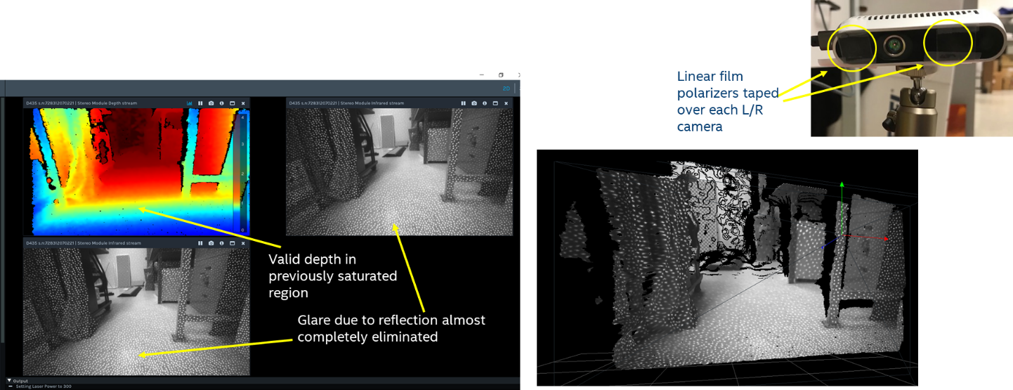
Figure 11b. Same scene as Figure 11a, but with polarizers mounted to the D435 stereo imagers. The glare and local saturation of the ceiling lights off the floor has been removed, and the depth map (on the right) no longer has a hole in the floor.
Another clear example of false depth artefact from specular reflection is shown in Fig 12. Some objects appear both as direct and reflected images. The reflections show up as depth objects that appear to be beneath the floor surface. The use of linear polarizers almost entirely eliminates the reflections and false depth with a negligible effect on the overall depth quality in the scene.
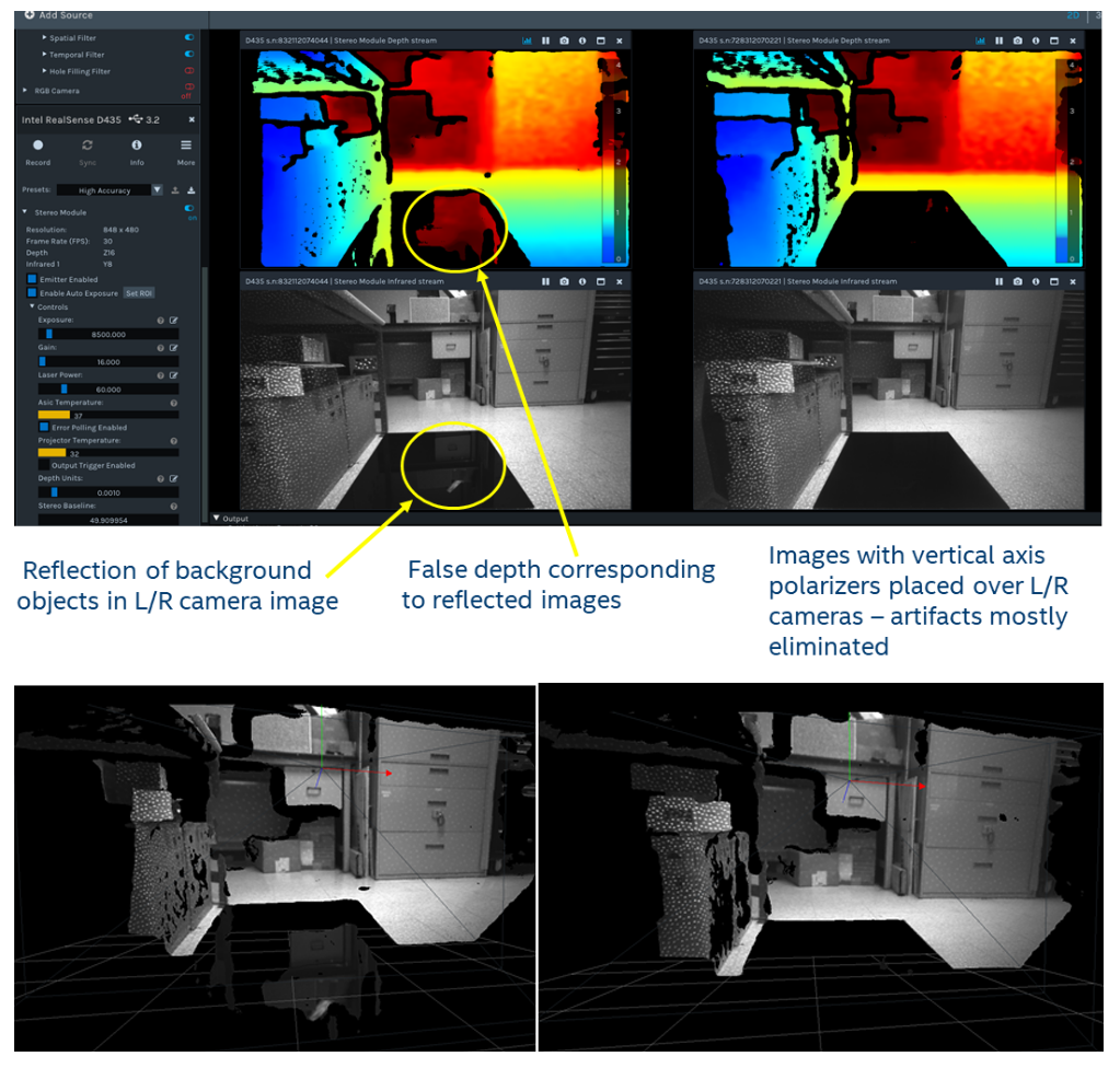
Figure 12a. Shiny floors or glass doors can also cause reflections which can lead to incorrect depth estimations. In this scene a cabinet is reflected in the floor and appears to be below the floor in the depth image.
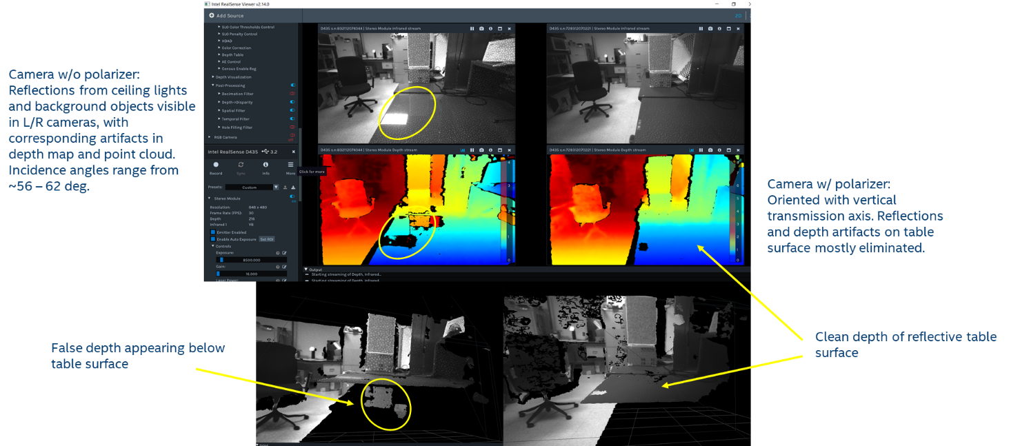
Figure 12b. A shiny table top shows objects in the background reflected and appearing below the table as well as local saturation from ceiling lights in the depth images. The use of properly oriented polarizers virtually eliminates both types of artefact.
While simple and inexpensive linear polarizers can be used in many cases to improve depth quality by suppressing artefacts, we do not include them standard on our cameras for a number of reasons:
- Image dimming: Placing any filter in front of a camera will reduce the brightness of light incident on the sensor. In the case of the polarizer, on average the brightness will be reduced by over 50%. This can be a problem in situations that are light-limited (e.g., dim ambient lighting and long range or low reflectivity objects) where exposure or projector power cannot be increased further, some degradation in overall depth quality might be introduced with the use of polarizers.
- Reflection angle dependence: The angle of incidence of the interfering reflection is an important factor in the effectiveness of this method. As illustrated in Figure 8, for shallow angles where the camera is pointed almost directly at the reflecting surface (up to ~20 degrees), the degree of polarization is low, but the reflectivity is also low (typically <5%), so the likelihood of reflection artefacts is fairly low. For very steep angles of incidence (>~70 deg), the degree of polarization is also low, but the reflectivity can be quite high. For such glancing angles, the effectiveness of polarizers will therefore be diminished. The upshot is that it is really only for incidence angles between ~20 – 70 deg where polarizers will be useful to suppress reflection artefacts.
- Orientation of polarizer: The optimal orientation of the linear polarizer with respect to the camera depends on the relative orientation of the camera and the reflecting surface. For example, for horizontal surfaces (e.g., floor or table), the filter axis should be vertical and for vertical surfaces (e.g., glossy/glass wall or window), the filter axis should be horizontal. Of course, if the camera is rotated, the filter axis should rotate accordingly with respect to the camera to maintain proper orientation. So the choice of mounting angle depends on the scene.
- Polarizer quality: Polarizers are available in a variety of types (e.g., film, birefringent crystal, wire-grid), but inexpensive film polarizers were used in the examples shown here and should work in most cases. The main consideration is the spectral range that the polarizer is designed for. The polarizer used here is designed for visible spectrum with a reduced but still usable near-IR extinction ratio. For scenarios that use predominantly near-IR light, a polarizer optimized in this wavelength range would be preferable.
This section has discussed polarizers used in front of the cameras. The IR projector uses lasers as the light source. Although laser sources are typically polarized, the type of lasers (VCSELs) used in the D400 stereo cameras do not have a well-defined polarization state and therefore do not exhibit any additional benefit from the use of polarizers or wave plates, above what has been described.
4.5 Need for Recalibration
In general, no re-calibration of the cameras should be necessary after the addition of optical filters, provided they are clear, reasonably optically flat, and creating no distortion or deflection of the image. The filters should also be thin and mounted as flat as possible, because any angle can cause a deflection of the image which can affect the alignment of the left-right images and degrade the depth quality or distance measurement. Also, care should be taken when mounting any transparent material in front of the camera if it also covers the IR projector, because back-reflection of light from the projector into the stereo cameras can significantly degrade their performance.
Since it is possible that some degradation of depth quality could occur after attaching optical filters, re-calibration can be used to improve the performance. There are different types of re-calibration that can be used, ranging from the simple on-chip self-calibration to full target-based factory recalibration. Normally the simple on-chip calibration should be sufficient to fully recover optimal performance.
5. Conclusion
This white paper has reviewed the primary types of filters that can be added to Intel RealSense Depth Cameras D400 Series for enhancing depth performance in certain corner-case operating conditions and environments. In some cases, it may actually be necessary to use filters of some kind in order to achieve desired performance or functionality and to suppress unwanted artefacts. In most cases, filters are added to the camera as needed and removed when not needed. However, for some applications where the use of filters will always improve performance, it is possible to build the filter into the camera either by permanently attaching it to the outside of the chassis, by attaching it to the inside of the chassis or directly onto the camera module itself. Custom designs, where the appropriate filter is designed and integrated into the camera are also possible. For example, in an indoor scenario where projector texture is required and range needs to be extended, a partially transmitting long-pass filter could be integrated permanently into each of the stereo camera lens assemblies.
6. References
- Stereo depth calculation paper. https://dev.intelrealsense.com/docs/tuning-depth-cameras-for-best-performance
- White paper on Projectors. https://dev.intelrealsense.com/docs/projectors
- We note that in some circles, cover glass slides or windows are incorrectly referred to as “lenses”. This usage should be avoided, as “lens” implies an element that focuses or diverges light.
- ND filter: https://en.wikipedia.org/wiki/Neutral-density_filter
- https://dev.intelrealsense.com/docs/tuning-depth-cameras-for-best-performance
- Polarizers https://en.wikipedia.org/wiki/Polarizer
- Fresnel equations: https://en.wikipedia.org/wiki/Fresnel_equations
- Brewster angle: https://en.wikipedia.org/wiki/Brewster%27s_angle
Updated over 2 years ago
