Stereo depth cameras for mobile phones
Intel® RealSense™ Depth Cameras for Mobile Phones.
Authors: Anders Grunnet-Jepsen, John N. Sweetser, John Woodfill
Revision 1.0
This article is also available in PDF format.
Abstract: We explore the value proposition of using miniature depth cameras for integration into mobile phones, examining in particular all the considerations that need to be taken into account to address front-facing usages such as enhanced 3D face authentication, background segmentation, hi-res 3D selfies, 3D avatar animation, and 2D photo enhancements (including scene relight) derived from use of 3D information.
1. Introduction
“Depth cameras” are cameras that are able to capture the world as a human perceives it – in both color and “range”, although some depth cameras only provide range maps. The ability to measure the distance (aka “range” or “depth”) to any given point in a scene is the essential feature that distinguishes a depth camera from a conventional 2D camera. Humans have two eyes that see the world in color, and a brain that fuses the information from both these images to form the perception of color and depth in something called stereoscopic depth sensing. This allows humans to better understand volume, shapes, objects, and space and to move around in a 3D world.

Figure 1. The output of a depth camera. Left: Color Image of a cardboard box on a black carpet. Right: Depth map with faux color depicting the range to the object.
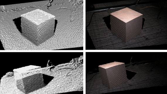
Figure 2. The 3D Point Cloud of the box captured in Figure 1. Left shows 3D mesh without color texture, and right shows the same scene with the image color texture applied. The top and bottom are different views seen by rotating the point-of-view. Note that this is a single capture, and not simply photos taken from different viewpoints. The black shadow is the information missing due to occlusions when the photo was taken, i.e. the back of the box is of course not visible.
In this article we will examine first how miniature depth camera could enable exciting new usages in mobile phones. We then present an overview of various depth sensing technologies and the considerations that need to be taken into account for mobile phone usages. We will examine in some detail the performance of Intel RealSense stereoscopic depth cameras, and will conclude by highlighting some of the key metrics that serve as the basis for characterizing and comparing performance.
2. Depth Cameras for Mobile Phones:
The 2D camera phone made its debut in year 2000 and was introduced in Japan by Sharp in the Model J-SH04. By 2013 the term “Selfie” was so commonplace that it was introduced into the Oxford English Dictionary. Today it is hard to imagine a mobile phone without at least one, if not 4, cameras. There has of course been the steady advancements over time of improving on the image quality in terms of resolution (the megapixels wars) and color quality, speed (frame rates), and low light sensitivity, to name a few.
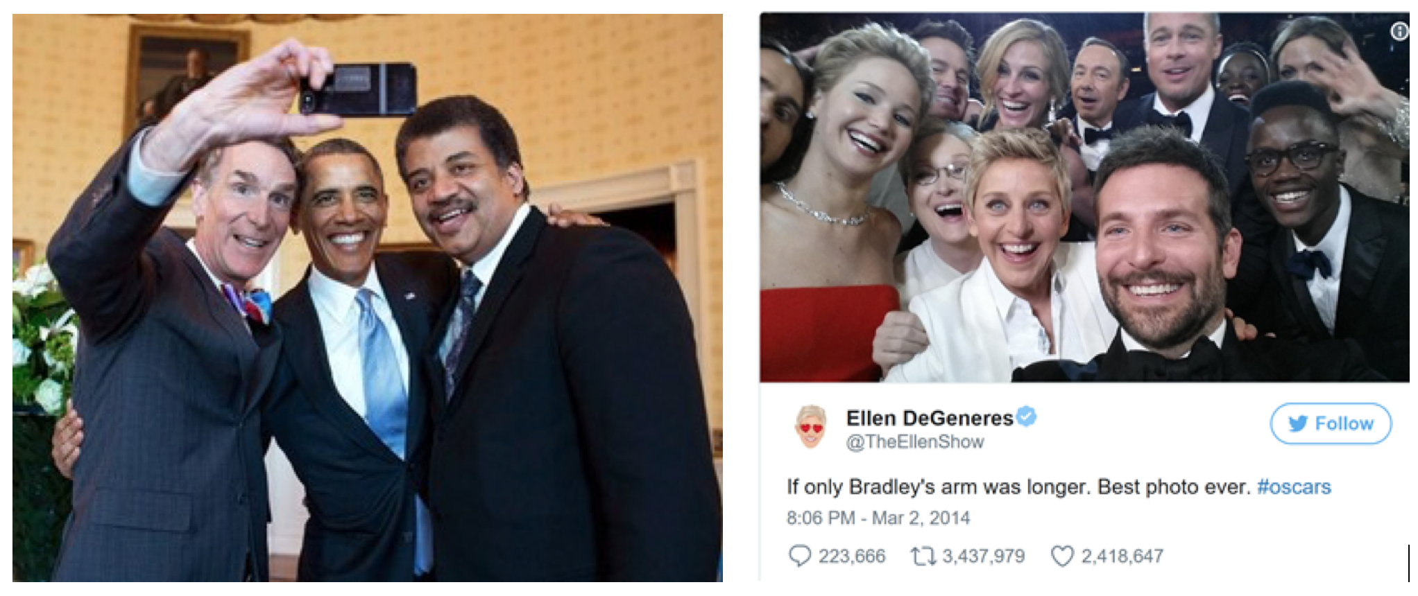
Figure 3. Bill Nye takes selfie of US President Barack Obama and Neil deGrasse Tyson at the White House1, and the “most famous selfie” by Ellen DeGeneres at the Oscars.
So what value can a user-facing Depth Camera bring to the mobile phone? Being able to capture one’s true likeness in 3D is of course better than 2D. This can be shared online as a 3D Selfie, or it can be enhanced in apps similar to Snapchat by allowing you to apply 3D filters that take into account the true 3D shape. For example, if you put on virtual elven ears or new virtual sunglasses or add a face tattoo in the app, they will look even more realistic as they rotate in space and get properly occluded as you move your head. 3D shapes can then also be inserted into apps or even be printed out via a 3D printer. Another usage is the ability to invoke a Privacy Mode, whereby only objects within a certain range of the phone would be visible. By applying this Background Segmentation you could be video chatting in a coffee shop and the people who walk behind you would not be visible. Perhaps the most important new usage is 3D-enhanced Face Authentication. By capturing the true 3D shape, dimensions, and color of your face, it is possible to create enterprise-grade spoof-proof User Login that is extremely convenient, moving us a step closer to a password-less world, not just for logging into your phone but for financial transactions as well.

Figure 4. A 3D-Selfie. The single photo was taken outside in full sunlight with a Depth Camera and is shown as a textured 3D point-cloud that is rotated to different views. Note that the true dimensions of the face are captured. In this picture anything beyond 0.6m was left out. For true Background Segmentation a more complex algorithm would be used that would yield cleaner edges and would use both RGB and Depth information.
In the next section we will explore how far away from reality this vision is, and what technology options should be considered.
3. Survey of Depth Camera technologies:
There are a variety of incredible technologies that are possible candidates for miniature depth cameras. We can start with the likely most familiar technologies. The Laser Range Finder that can be found in a hardware store currently only provides a single depth point, but comes in two variants that illustrate very well two common techniques: Time-of-Flight and Triangulation. In Time-of-Flight, or ToF, a single ultra-short pulse of light is emitted and a co-located detector then measures the arrival time of the beam reflecting back from the object. The farther away the object, the longer the return time. Conversely, this technology measures the speed of light if you know distance to the object. However, it is difficult to achieve sub-millimeter measurements with this technique and so for objects that are near it is common to use the triangulation technique.
Triangulation dates back to antiquity and the beginnings of trigonometry in ancient Egypt. It was, for example, used to measure the height of the Pyramids by measuring their shadows and comparing them to the shadow from a vertical stick of known height. Laser range-finding triangulation works by placing the laser and detector a certain distance apart, which we call the baseline distance. The laser pointer emits a beam that hits the object. The detector images this object and in general the detector can only see the laser beam (everything else is black). By measuring where the laser beam spot appears on the sensor it is possible to measure the distance to the object based on the triangle laser - object - detector. The more the beam has displaced from the center, the closer the object is, as shown in Figure 5.

Figure 5 Left: Time-of-flight single-point laser range finder. Measuring the time for a pulse to be transmitted, reflected and detected will reveal the distance to the object. Right: Laser range finder based on triangulation. As the object distance varies, so does the spot location on the sensor. In this case, the closer the object, the more the spot is displaced to the right on the sensor. Structured Light and Stereoscopic depth sensors rely on the same triangulation principles.
Both of these techniques have been perfected over time and variants have been developed to measure not only a single point, but well over a million points per second. Pixelated ToF sensors have been embedded in products like the Microsoft Kinect One, for example. In this product a “Flash” of light illuminates the whole scene and thousands of small sensors individually measure the return time from different parts of the scene. Another variant on this is the scanning "Lidar" used in some automobiles where a single beam (or perhaps a few beams) is scanned across the scene and a depth map is built up over time. Triangulation-based sensors have also evolved into many variants. For example in “Structured Light” sensors 10’s of thousands of spots (or patterns of spots or lines) are emitted and individually triangulated. The original Primesense-based Kinect sensor uses this technique. “Coded-Light” is another technique which builds on structured light concepts by using patterns that vary over time and compositing finer detail depth from multiple images. Finally we return to the way that humans see depth, via stereoscopic imaging. This is also a triangulation technique, but instead of needing to know exactly what pattern of light is being emitted, electronic stereoscopic vision systems simply match image patches in the left eye (i.e. camera) to image patches in the right eye. The objects that are closer are displaced more in the horizontal axis. Stereoscopic vision is the only technique which can be truly “passive” meaning that no light needs to be emitted. In the special case where a scene has no intrinsic texture, like a plain white wall, this type of sensing can be problematic as matching left and right image patches becomes ambiguous. In this case a laser can be used to project a texture. This is called “assisted” stereo vision or sometimes “active” stereo. However, a priori knowledge of this pattern is not required for stereo vision, unlike structured light approaches.
For completeness, we should also mention another couple of techniques that use a single sensor and no laser emitter. One approach is called “Structure-from-Motion”, SfM. This is quite similar to stereoscopic vision in that as a user moves the camera in space, the camera can effectively take an image at point A and another at point B a little time later and treat them like two stereoscopic images. The challenge is knowing how much the camera has moved and what direction they are pointing at both points, and of course it assumes that the scene does not change over time. This is what monocular SLAM algorithms (Simultaneous Location and Mapping) are all about2, and they usually augment their performance by fusing their data with other sensors, such as inertial measurement units, or IMUs, that consists of electronics gyroscopes and accelerometers that can measure changes in angle or speed. Another approach gaining traction is Machine Learning. The core premise is that with enough prior knowledge of world scenes that have been tagged with ground truths, a computer can be taught to infer a depth from optical clues. This is similar to asking the question: “How can humans drive a car if they close one eye?” Beyond stereo vision, there are a lot of monocular vision cues that can be used, including motion parallax, depth from optical expansion (objects get larger as they move closer), perspective (parallel lines converge in the distance), relative size, familiar size, accommodation (focus/blur), occultation (objects that block other objects are perceived as closer), texture gradients, and lighting and shading, to name just a few.c These cues tend to be very good at understanding relative depth, but not as good at quantitative absolute depth.
In principle all these technologies can be miniaturized to fit physically inside a mobile phone, but some are better fits than others in terms of the maturity of optimizing solutions for phone integration and for application-specific mobile phone usages. This is a key point: Phone companies have to keep size, cost, weight and heat to a minimum to maintain a cardinal rule of Mobile Phones – Mobility and Ease of use.
In the following sections we drill down on the requirements of depth sensors for mobile phones, and then introduce the stereoscopic solutions comprising the Intel RealSense D4xx family of Intel RealSense depth sensors which have been optimized for indoor and outdoor usages for mobile phones, drones, robots, augmented/virtual reality (AR/VR), and surveillance applications. We then conclude with a more detailed explanation of how to characterize and quantify the depth performance.
4. Requirements for Mobile Phone usages
Mobile phones are amazing feats of technology integration. As we consider adding a depth sensor to mobile phones we need to focus on balancing 1. Size, 2. Power/thermals, 3. Cost, and 4. Performance framed around the intended usages. All are intimately tied together and require a complex trade-off analysis. Performance is by itself a very intricate and nuanced discussion. For example, an optimal solution would have high frame rate for real-time usages of background segmentation and 3D capture, and a high X-Y spatial resolution for good background segmentation, and a high depth resolution (Z-axis) for good 3D depth for face authentication and 3D selfies. It should ideally also provide a fully hardware synchronized and pixel-matched calibrated mapping between depth and color (or IR image) which is critical for good background segmentation. Expanding on depth performance, we note that this can essentially be bucketed into two questions: 1. “What can the depth camera see?” and 2. “What is the error on what it can see?.”
Structured Light, ToF, or Stereoscopic depth camera technologies all have tradeoffs in performance so it is important to understand what they can and cannot see. For example, while starting an analysis by looking at plain walls is very informative (as we will see in section 6), for the 3D selfie usage it is arguably more important to be able to see all objects that could appear in a common scene. Since faces may be adorned or have hands and jewelry in them or silk ties (as in the Ellen Selfie in Figure 1), it is important for the sensors to be able to see dark hair, full black beards, leather gloves, glasses, cloths that absorbs IR light, shiny metal objects, jewelry, hats of different material, masks, and various skin colors and make up. Many early sensors did great on the important clean-shaven bald white man demographic, which is of course not enough. “Active” solutions that rely on seeing the reflected beams of light can find many of these examples quite challenging. This is especially true in bright outdoor environments where sensors need to compete directly with sunlight to see the reflected beams. The effects of sunlight can be somewhat mitigated by shifting to 940nm light, by using global shutter sensors and time gating the emitted/detected light, and by simply increasing the power of the laser projectors. Beyond power concerns, the latter approach has hard limits associated with eye safety which is clearly paramount. Another question is usability around whether more than one phone can be used at the same time near one another. Many active sensor technologies suffer from cross-talk issues because the beams they send out contain important information that will interference with other mobile phones. Good stereoscopic solutions, however, do not suffer from any of these drawbacks as they see most objects, work well completely passive, and work extremely well in bright sunlight, and even under water.

Figure 6A. The outdoor 3D selfie, needs to see the user as well as the background. The point-cloud shown on the right was down-scaled on purpose to show grid lines. This capture was made with the miniature Intel RealSense D405 module intended for mobile phones.

Figure 6B. An example of a capture with a Intel RealSense D435 Camera, showing a depth map on the left for a traditionally difficult scene that included dark carpets at various angles, shiny black metal bowl, specular plastic ball, and black leather purse with metal zipper.
Other factors to consider are sensitivity to motion of both the user and the scene. To combat this, the sensors generally have to support short exposure times and be very sensitive to low light. Global shutter sensors are a nice solution but the trade-off tends to be larger pixels and more cost and result in solutions that are much larger, in particular in lens height which is critical to achieve thin mobile phones. Related to size is also the choice of baseline. For triangulation-based sensors the depth resolution improves linearly with the distance between the sensors, but this obviously increases the size of the solution and there are limits to placements of sensors in mobile phones. Turning to operating range, users would of course like to have a small minimum range (aka Min-Z) for those really near close-ups, as well as a large max range so they can capture the background as well. Active solutions do well in near range but generally do not see well beyond a few meters at which point the reflected IR light pattern becomes too weak to be visible.
Another category of challenges is associated with artifacts that stem from the measurement techniques. For example some geometric shapes or edges can cause problems and not be properly resolved. For example, ToF solutions tend to suffer from sensitivity to multipath interference, which means that the reflected pulses can come from multiple objects after multiple reflections. This manifests itself in such artifacts as convex right-angle corners being captured as quite “rounded”. There is also a large problem for any scene that has retro-reflector “cat’s-eye” tape in it, which is not an uncommon addition to hats or clothing in northern Europe. Stereoscopic sensors do not have any issues with these cases, but do have a problem with very precise periodic patterns, where spatial aliasing can lead to misreporting the depth values. Another big challenge is the dynamic range of the sensors. It is important to be able to calculate depth to all parts of a complete scene, even if it has large intensity (reflectivity) and depth variations in the same image, like faces with black make-up or dark glasses, or a person standing in bright sunlight with dark shadows under hats or chins. This becomes especially difficult for active systems because image brightness scales as the square of the distance away and it therefore sees a very strong variation with distance. Ideally a system should be able to capture depth at a wide range of distances and not just in the plane of the face. This is similar to trying to take a close-up selfie in the dark using a flash – parts of the image will be visible and part slightly farther back will be very dark. Passive systems do a much better job in these scenarios as they rely on ambient illumination and do not suffer from this saturation, unless they turn on their flash of course.
This brings us to the importance of how well or with what error object distance can be measured. For all triangulation techniques it is important to understand that the error grows quadratically with distance away. The beneficial corollary is of course that objects that are near have higher depth resolution which is why triangulation is favored for sensing near objects. So when the question is asked “What is the range of the depth sensor?,” for passive stereoscopic solutions one could answer “infinite”, as these systems will see extremely far, just like humans can see objects as far away as the moon, the sun, and the stars. The important thing is to report the right value for depth of course, but this is where the answer of maximum range becomes specific to the application. Capturing a face in 3D needs very high depth resolution, but background segmentation can cope with much more depth error. In general, all triangulation-based techniques have smaller depth error with larger baseline, larger sensor resolution, and smaller field-of-view (i.e. optical zoom) and can therefore be tailored for specific usages. Furthermore, most depth sensors can benefit from averaging the measurements over time, where the application usage permits it.
While we have focused so far on how important depth errors are for objects that are visible, it is equally important that a system not report seeing something that is not there, i.e. “hallucinating”. Many ToF solutions will, for example, have lots of spurious depth points or salt-and-pepper noise that are simply false readings, and need to somehow be filtered away in post processing. Many ToF solutions may also show a “spray” of depth values near edges because the ToF pixels are recording depth from both the near object and the background at once.
In the next section we look at how Intel’s RealSense Stereo Depth Cameras can offer a rich balanced solution and design freedom to cater to mobile phone integration and usages.
5. Intel RealSense Stereo Depth Camera
Intel has been developing depth sensing solution based on almost every variant of depth sensing technology for several years, and all technologies have their technological tradeoffs. Of all the depth sensing technologies, stereovision is arguably the most versatile and robust to handle the large variety of usages. While one could be tempted to think that stereoscopic vision is old-school technology, it turns out that many of the challenges faced by stereo depth sensing in the past have only now been overcome – algorithms were not good enough and prone to error, computing the depth was too slow and costly, and the systems were not stable over time.
How have we arrived at today’s stereovision solutions? Stereoscopic depth sensing was first explained in 1839 by Charles Wheatstone as he invented the stereoscope, which is a predecessor to the ViewMaster kids’ toy. In Figure 7 we give a brief overview of the concept showing how a stereo pair of left and right cameras will see different views. The key point to notice is that objects that are closer will experience a larger shift along the horizontal, or epipolar, line. This shift is known as the disparity and we can calculate disparities for every point in the scene, as seen in Figure 7 where the pixels on the near-range balloon have a larger disparity than the ones on the building in the background. Finding matches between left and right image patches is known as solving the correspondence problem. The depth map can then be calculated from the disparity map through simple triangulation. Note that in practice the disparity search along the epipolar line is usually limited to a certain number of pixels simply due to calculation limitations. Normally this is 64 to 128 pixels in an electronic system. The upshot is that there is limitation to how close objects can be to the camera, or they match will not be found. We call this the Minimum Distance, or MinZ.
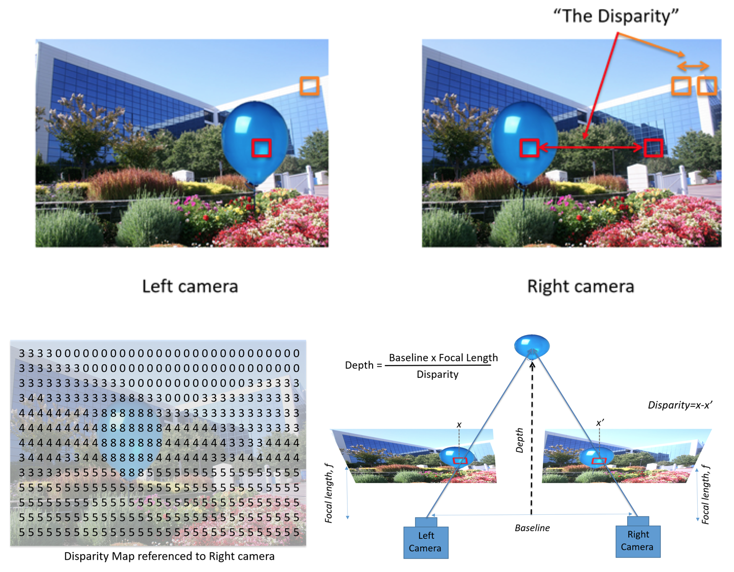
Figure 7. Stereo depth perception. The left and right images will see the same scene from different viewpoints. Objects that are closer will shift a certain number of pixels (or disparities) along the horizontal axis (epipolar). The resulting disparity map can be converted to a depth map using triangulation.
Computer stereo vision became a very prominent area of research in the 1980s, and was kicked off by early efforts such as Marsha Jo Hannah in 19744. Algorithms to better understand depth made great advancements, and the Middlebury Benchmark to compare stereo algorithms with respect to accuracy was established in 2002, followed by the KITTI dataset in 2012 for outdoor navigation and robotics benchmarking. 5,6 By providing an open-source set of stereoscopic images annotated with laser-scanned ground truths, it became possible to compare the performance of different algorithms on a common playing field and to see a steady progression of improvements over time. The performance of state-of-the-art stereo depth algorithms has become quite impressive but it has in general come at the expense of ever increasing complexity and processing power. Some of the best algorithms can take several minutes to calculate depth from single pair of 2MP images, even on 4 cores of an i7, consuming 10’s of Watts of power.

Figure 8.
LEFT: Intel RealSense D4m vision processor.
MIDDLE: Example of one of the Intel RealSense D4xx series depth modules encased in a steel case.
RIGHT: Intel RealSense USB3 Depth Camera D435.
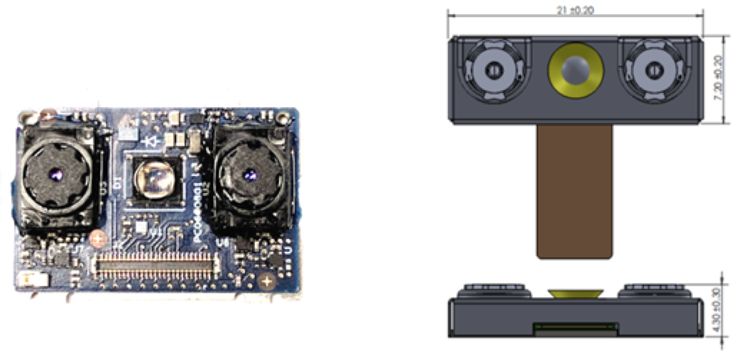
Figure 9. The Intel RealSense D405 Mobile Form-factor reference design showing two imagers sensitive to IR and RGB light, with a 15mm baseline, and an IR flood illuminator in the middle for operation in the dark. This design was optimized for user-facing mobile phone usages for small size, cost and power, and can be complimented with additional structured (texture) light projector if desired, but is generally not necessary for most mobile phone usages.
Intel has greatly accelerated this compute by creating custom silicon for depth sensing7 that can achieve calculation speeds of over 36 Million depth points/second using a customized variant of a Semi Global Matching algorithm, achieving frame rates of >90fps, using less than 22nW/depth-point in a chip package size of 6.3x6.3mm which is a fraction of that of the Intel Core i7, and searching across 128 disparities. The goal was to enable computer stereo vision to achieve performance levels (power, thermals, resolution, frame rate, size, cost etc.) needed for embedding in small consumer electronic devices such as mobile phones, drones, robots, and surveillance. With this goal in mind, Intel is now on its 2nd generation ASIC that shows great improvements especially in environments where the projected light of any active system (assisted stereo, structured, or ToF) would be washed out or absorbed, outside or on dark carpets that tend to absorb IR light, as seen in Figure 10.
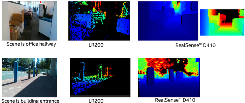
Figure 10. Example scenes comparing the previous generation Intel RealSense LR200 Module vision processor performance with the new Intel RealSense D410 Module and vision processor showing the vast improvement in one chip generation.
One very important trait of a great stereo depth algorithm is the ability to achieve a subpixel accuracy of <0.1. This means finding the correspondences in the left and right images and matching their location to much better than a fraction of a pixel resolution. Intel’s algorithms routinely achieve 0.05 sub-pixel accuracy for well textured passive targets, but in general the accuracy can vary and will be worse for objects that have little or no texture. One of the important and most publicized limitations of passive stereo systems is that it has difficulty finding correspondences (and hence depth) on objects that have very little texture, like a completely clean white board. The better the optical systems (image quality) and the algorithms, the better they are at teasing texture out of difficult scenes using information from multiple color channels, but there are still corner cases that can be very challenging. In this case it can help to use an external projector to project a beam of light that creates a texture on the scene, for example by projecting 100’s of thousands of small spots at pseudo-random locations. In this configuration the system is known as “assisted” or “active” stereo and is very similar in performance to structured light systems. The main difference is that for active stereo the pattern is not critical and does not need to be calibrated to the laser, and the spots need not be much brighter than the background image. This is one of the traits that make stereo systems so robust to interference and allows multiple units to easily coexist in close vicinity of each other.
As mentioned, texture can be projected onto a scene using a miniature projector. The wavelength chosen is usually >850nm IR light that is invisible to humans. Intel has developed a few different versions that can be paired up with different imager combinations for best performance. Looking at Figure 1 will in fact reveal that a patterned projector was used. One important aspect of a laser-based projector is that the coherence of the source needs to be reduced significantly to reduce the deleterious effects of laser speckle. However, it should be noted that even the best projectors with speckle-mitigation circuitry tend to show >30% worse subpixel performance than well textured passive targets (subpixel RMS is ~0.07 vs ~0.05).
We turn now to another extremely important aspect of product viability, namely stability over time. Triangulation techniques are very sensitive to distortions in the optical system over time. For example, for structured light it is critical that the projection pattern not change over time or temperature, while stereo systems are impervious to this. However, for both stereoscopic and structured light systems any changes over time in the optical intrinsic properties (imaging lens location and pointing angle) and extrinsic properties (bending angles between the left-right imager for stereo or laser+imager for structured light) need to be minimized or it will impact the depth quality and accuracy. This can be partially addressed by building a miniature optical system that is mechanically isolated from the outside world so it is not impacted by external forces. This can best be done by encasing the optical head in a metal stiffener, as seen in Figure 8, and mounting it at a single point with a small standoff. Unfortunately this needs to be balanced with the need for heat dissipation which benefits from thermal contact, especially if a laser projector is used. An additional approach is to develop dynamic calibration algorithms that can routinely check the calibration quality and correct for it, preferably with minimal user intervention.
When engineering the best ultimate solution it is also important to optimize using all the tools of the trade, and this includes post-processing. For example, trying to minimize the cost or size of an optical depth sensing system may result in sub-optimal performance of the raw per-frame depth, but if this can be recovered by applying some post-capture filtering then this is a design freedom the engineers will want to explore. Figure 11 shows two different cases where the raw instant frame depth has reduced performance, but a small amount of temporal and spatial filtering recovers the performance.


Figure 11. Post processing of images can be used to clean up a depth map, as in this 3D selfie and office cubicle scene.
Top: In this example we show how a small baseline stereo imager (the Intel RealSense D405) with a somewhat noisy depth map can be cleaned up by applying a small amount of spatial and temporal filtering.
Bottom: Intel RealSense D410 3D capture of an office cube with minor post processing using exponential moving average and edge-preserving domain transform filtering.
Returning now to the specific case of mobile phone usages, a system design should of course be small, low power, low cost, and be able to generate good depth in all environments and lighting conditions. For face authentication and unlocking your phone in particular, it is important that users be able to use this feature indoors and outdoors, but also in very dark environments – watching television, waking up at night, walking the dog outside in the dark. For the facial unlock to work in the dark we need to illuminate the face. This should preferably be with IR light, or the user will be constantly blinded by visible flashes. It turns out that good facial authentication relies heavily on both 3D depth AND greyscale (or color) 2D image quality. So it is not desirable to use structured light to illuminate the face for face authentication, as the face image will be polluted with this pattern. While some patterns can be partially removed in post-processing with degraded overall performance, ideally the system should have an IR flood illuminator to uniformly light up the face.
We will conclude this section with an overview of the flexibility of design for stereoscopic systems. Figure 12 shows an example of a few different designs of depth sensors that all use the same RealSense Vision Processing Unit. Why are so many different designs used? The key is that performance can be optimized under different constraints because stereoscopic systems are extremely customizable and adaptable and can benefit from a large optical industry of COTS. This is also very important for industrial designs considerations. For example, if long range and high quality are paramount and the product is less sensitive to price, it will be possible to use higher performance CMOS sensors (higher dynamic range, more sensitivity and higher quality) as well as better and larger optics so that the input images are of high quality. In the other extreme where cost and size are critical, it is possible to use small baseline, cheap consumer-grade CMOS sensors, and plastic optics, as in the case of the Intel RealSense D405 shown in Figure 9.
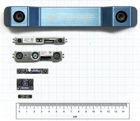
Figure 12. A collection of Intel RealSense D4xx camera modules that all use the same ASIC.
In general the main design parameters are 1. Baseline, 2. CMOS selection (resolution, global vs rolling shutter, HDR, color vs greyscale), 3. Field-of-View (FOV), and 4. Quality of lenses. Figure 13 shows some examples of different RealSense modules and their theoretical performance variations. These RMS error curves will decrease with larger baseline, narrower FOV, and higher resolution. Note that each system has a different Minimum distance (shown in Figure 13 right side) but that the minimum distance will decrease and scale linearly with the horizontal resolution mode during operation, meaning that a module that has MinZ=50cm at 1280x720 resolution will have a MinZ=25cm when operated at 640x360, but will also have 2x worse RMS depth error. As seen in Figure 13 Right side, at near range it is actually possible to achieve well under 1mm depth resolution.

Figure 13. Design curves for the RMS spatial error metric for different model (right side plot is for shorter range). For the smaller baseline models sub-1mm resolution can readily be achieved. The smallest module is the Intel RealSense D405 (using Intel RealSense D4m VPU) which has a baseline of 15mm and a 68x53 portrait-mode FOV.
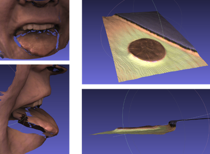
Figure 14. Intel RealSense D405 mobile module modified for focus at 6cm range, showing a 3D snapshot of a mouth, and a penny placed near mouse mat. The RMS error was about 60 microns. This was achieved with no external projector usage.
6. Evaluating Performance: Measurement metrics and methodology
Regardless of the specific technology used to produce the depth image, there are a few fundamental aspects of depth camera performance that can be used to evaluate the quality of the images generated. In addition to traditional image characteristics such as spatial resolution and color quality, depth images are typically evaluated based on how well they reproduce the depth properties of the scene. In particular, depth accuracy is clearly important – how close is the computed depth to the true depth for each pixel in the scene.
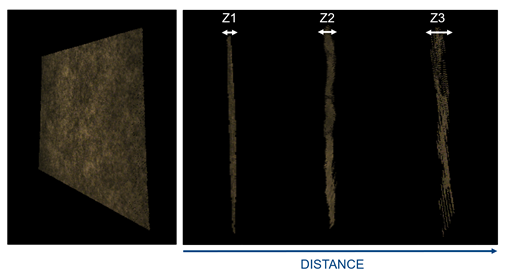
Figure 15. Example of measuring absolute depth accuracy and the spatial RMS error. This illustrates a well textured wall measured at different distances. The farther away the wall, the larger the RMS error, as seen by the side view measurements of the spatial RMS error Z1<Z2<Z3.
A related characteristic is the variation in computed depth errors across the image. This provides a measure of how “smooth” the image is, assuming a smooth scene, i.e. spatial noise. Analogous to spatial noise is temporal noise, or how much variation over time (typically frame-to-frame) there is in the depth data, given a static scene. A fourth basic metric is simply the number (or fraction) of valid depth pixels, regardless of how accurate their values are, referred to here as fill ratio. Under some conditions, there is insufficient data to determine a depth value for a particular pixel and therefore the pixel is labeled as “invalid” and is typically represented as a missing or dark depth pixel in the image. While it is generally assumed that a larger fill ratio is better, in some cases it is preferable to have an invalid pixel versus one that has significant error. In others, where accuracy is not as important, a valid yet inaccurate pixel is better than none at all. For stereo based depth cameras in particular, the algorithm used to compute the depth can be adjusted, or tuned, resulting in varying fill ratios, usually as a tradeoff with other performance metrics. Other depth metrics are sometimes computed and used to evaluate or qualify camera performance, but most are related to or derived from the basic metrics described above which are defined in more detail below.
A related concept to depth performance metrics is that of Maximum Range, or how far can the depth camera see. In principle, this seems like a simple concept, but in practice, the answer is typically – “it depends”. Specifically, Max Range depends on which performance characteristic is limiting the range. The one that is most important for a particular application is typically the one that will determine the practical range of the camera. This concept will be discussed further in the following sections.
Basic Depth Metric Definitions
Z-error, or absolute accuracy: Measures how close the reported depth values are to the actual distance (ground truth, GT). Z error may be defined in a variety of ways but most definitions are based on differences (which may be signed or magnitude) between measured depth values (per pixel or averaged over an ROI) and GT.
Spatial Noise, or relative error: Measures the variation in depth values across an ROI assuming a flat plane target. This metric is independent of the accuracy of the depth values. Ideally, a flat target is used to measure the spatial noise and it is typically defined as a standard (or RMS) deviation of the distribution of depth values. If the camera is aligned parallel with the target, the distribution of depth values may be analyzed directly. Otherwise, the data must be fit to a plane before analysis.
Temporal Noise: Measures the variation in depth values over time. Temporal noise may be defined as a standard deviation in depth values over a specific number of frames (e.g., 10). It is typically measured per pixel and then an average or median is taken over a specific ROI to represent the temporal noise for that device and ROI.
Fill Ratio, or Valid Pixel %: Measures the portion of the depth image containing valid pixels (pixels with non-zero depth values). This metric is independent of the accuracy of the depth values. It may be defined over any particular region of interest (ROI).
Performance Metric Measurement Methods
In this section we look at how some of these metrics should be measured, with main emphasis on how this can be extended to a production line for pass-fail criteria. However, it is very important to note that this is a subset of all the different metrics that should be evaluated to understand the full performance of any depth camera technology, and care should be taken to not highlight one simple test, like the indoor flat-white-wall test, over more realistic depth scenes. For example, a camera can be tuned to provide excellent results on a flat-wall by strongly leveraging hole-filling, temporal averaging, and spatial averaging depth filters, but the tradeoff is likely to be that non-flat real shapes (ex: spheres, heads) end up becoming quite distorted and flattened. While this type of complete technology evaluation will not be described below, it is recommended that usage specific tests should be incorporated in a test flow and may include using a mannequin head or various geometric shapes and materials and colors (balls, rubber hands, sticks, carpets) at varying distances, for example.
With that being said, the basic depth metrics of the previous section may be determined in a number of ways but it is recommended that a common environment and methodology be used in order to simplify the testing and minimize errors. A common philosophy is to start by measuring under simple optimal conditions that are as unambiguous way as possible. This environment can be described generally as a flat surface that is placed at a controllable and known distance from the camera under test. For active systems (ToF, Structured Light, Active Stereo), the target surface is smooth with a uniform, non-glossy (diffuse) finish yet with high reflectivity. A flat white wall painted with a flat (or matte) white paint is a simple example of an acceptable test target. Alternatively, white poster board mounted to a rigid frame or structure may also be a suitable target. These tests are usually also done in low light. In most cases, a flat surface target, like a wall, aligned parallel to the depth camera is used in order to simplify the measurement since GT may be well approximated from a single measurement using an independent absolute measuring device such as laser rangefinder or tape measure.
In the case of a passive stereo system where with no projector (or projector turned off), a passive test may be performed, in which case the target must also provide a sufficiently textured pattern. In this case special textured targets, as shown in Figure 16. Sufficient ambient lighting is also required when performing passive tests, but this should not require more than typical room lighting. This pattern should emulate nature by having texture on many scales (be fractal in nature), so that measurements can be done at different distances.
An example of a depth performance test system, used for Intel RealSense cameras, is shown below.
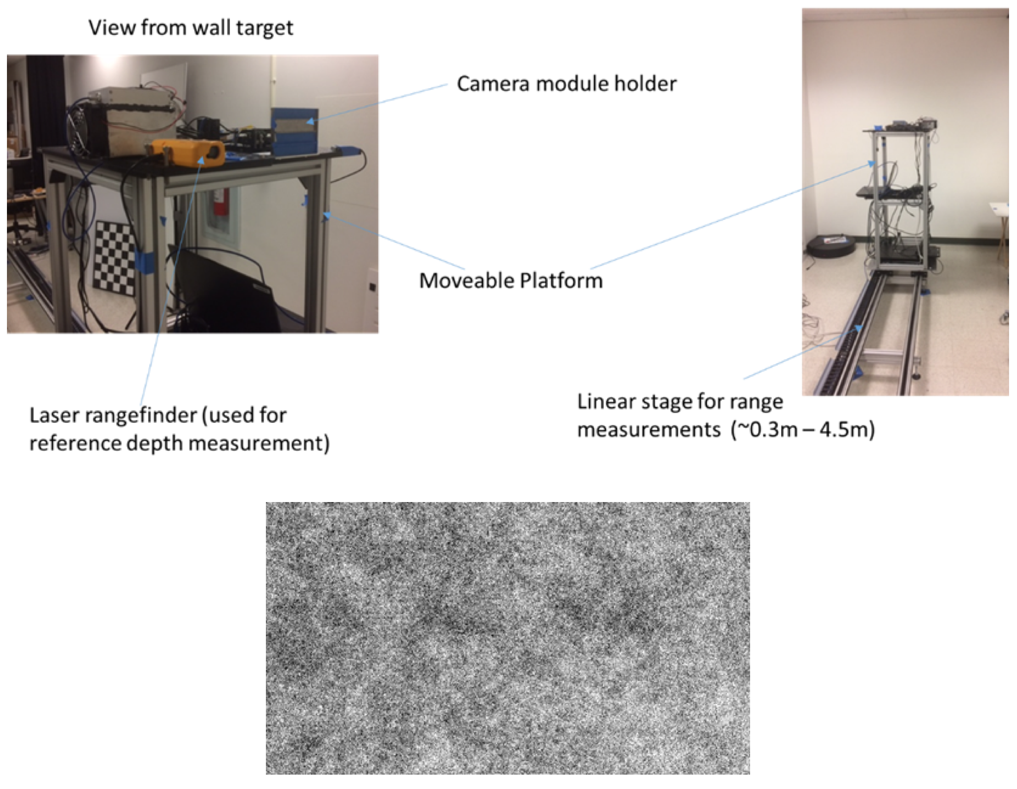
Figure 16. Sample systems used for characterizing the performance of a depth sensor. The pattern in the bottom is an example of a pattern used for passive stereo testing.
Depth metrics are typically measured in one of two ways: a) by capturing depth images from the camera and then analyzing the data in a separate, typically off-line, process; or b) performing the image capture and metric analysis in real-time using a dedicated tool designed for depth performance measurements.
Sample Intel RealSense Camera Performance Data:
Using the test system and methodology described above, basic depth metrics are measured for Intel RealSense cameras. The standard measurement condition is a controlled indoor environment with typical ambient lighting (e.g., 100 – 200 Lux of overhead fluorescent light). Measurements are performed at various distances from the flat target, from near the camera’s Min Z to the longest practical distance, usually limited by the size of the available target. For the data presented here, the maximum distance for full image data is 1.5m – 2m, depending on the camera’s FOV. Beyond this distance, a reduced ROI is used to compute the metrics.
A typical scan of absolute Z error for Intel RealSense D410 depth cameras (with 55mm baseline and 65 deg horizontal FOV) is shown in Figure 17. The camera is operating at 30 fps, 1280x720 resolution, and a projector optical power of 210 mW. In this case, the mean error over the respective ROI is measured (Full = full FOV, Center = central 40% of FOV). The dashed line indicates an error of 2% of the actual distance, below which is considered acceptable for most applications.
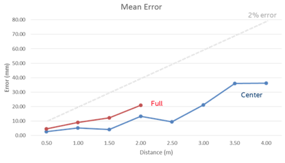
Figure 16. A typical scan of absolute Z error for Intel RealSense D410 depth camera. The Full and Center are aggregate results for different parts of the full depth map.
A similar measurement of the spatial noise under the same conditions is shown in Figure 18. This represents the amount of variation in depth values across the ROI, as measured by an RMS deviation from a plane fit to the data. Spatial noise of <1% is generally achievable out to 4m over the center ROI. Note that as we approach and RMS error of 1mm at close distance the planarity of the large target becomes increasingly important for proper measurements, and very special care needs to be taken to get correct results.
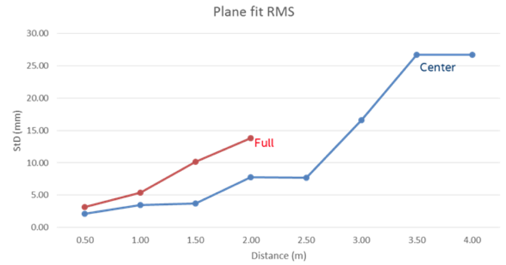
Figure 18. A typical scan of spatial noise RMS error (StD) for Intel RealSense D410 depth camera.
Fill ratio is primarily limited by the available signal (i.e., light from a well-textured scene). Under test conditions similar to the measurements shown above, where the projector provides all the signal to the camera, fill ratios >99% in the center ROI are achievable beyond 4m. A typical Intel RealSense D410 depth map with 100% fill ratio over the center ROI at 4m is shown in Figure 19. The projector electrical power is 300 mW but ~100% fill is achievable at powers as low as 180 mW at 4m. The depth map also gives an indication of the spatial noise across the image (~0.7% in this case).
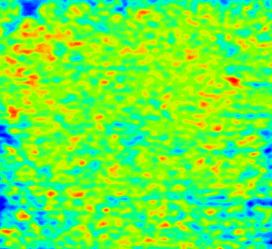
Figure 19. Depth map contour plot at 4m range for a flat white wall using a patterned projector. The RMS variation in depth is ~0.7%.
Passive performance under the same conditions on a well-textured wall is typically better than the active performance shown above.
“Range Anxiety” - Long Range Operation
For distances beyond ~4m, Intel RealSense D410 cameras continue to perform well with performance that falls off with distance generally as expected and can be extrapolated from the shorter range data. Laboratory (indoor) testing up to ~8.5m has been done over a reduced ROI and projector-limited fill ratios of >99% are seen up ~7m for HD resolution and longer for lower resolutions.
Regarding the question of maximum range, the specific Max Z depends on the limiting performance metric. For example, using <2% error and <1% RMS noise as upper limits, typical Intel RealSense D410 range is ~6 – 6.5m. Increasing or decreasing the acceptable performance limits will of course increase or decrease the Max Z. If fill ratio is the limiting metric, then range beyond 7m is achievable. Of course, outdoor operating range will generally not be limited at all in terms of fill rate, but error-based range will have similar, or slightly better, limitations as indoor.
7. Summary
The use of depth sensors in mobile phones for user facing application is gaining a lot of momentum based on the many compelling usages that we have outlined. Many depth sensing technologies can potentially be miniaturized and employed for these usages, including Structured Light, Time-of-Flight, and active or passive stereo. We have presented the case here for the use of specific Intel RealSense stereoscopic depth sensor modules, such as the Intel RealSense D405 reference design with a 15mm baseline, which is a great candidate for fitting the spatial constraints and performance requirements, and is in general extremely flexible to design modification that can adapt it to a design space of size, power, cost, and performance.
8. References
- By The White House - https://www.flickr.com/photos/obamawhitehouse/14081505711/, Public Domain, https://commons.wikimedia.org/w/index.php?curid=32567572
- https://www.doc.ic.ac.uk/~ajd/Publications/davison_iccv2003.pdf
- https://en.wikipedia.org/wiki/Depth_perception
- Marsha Jo Hannah, “Computer Matching of Areas in Stereo Images”, AIM-239, July 74 (PhD Thesis).
- http://vision.middlebury.edu/stereo/data/
- http://www.cvlibs.net/datasets/kitti/eval_stereo.php
- “Intel RealSense Stereoscopic Depth Cameras”, L.Keselman et al, 2017 https://arxiv.org/abs/1705.05548
Updated over 5 years ago
